Power system MCQ with Explanation 2021 | Objective Type Question OF Power system with Explanation
Ques 1. A shunt reactor at 100 MVAr is operated at 98% of its rated voltage and at 96% of its rated frequency. The reactive power absorbed by the reactor is
Ques 2. A single-phase transformer with a 2-kVA rating has a 480-V primary and a 120-V secondary. Determine the primary and secondary full-load currents of the transformer.
4.17 A and 16.67 A
10 A and 13. 2 A
6 A and 16.67 A
Insufficient Data
Answer.1. 4.17 A and 16.67 A
Explanation:
Primary full-load current = VA rating / Primary Voltage
Primary full-load current = ( 2 kVA * 1 000 ) / 480 V = 4.17 A
Secondary full-load current = VA rating / Secondary Voltage
Secondary full-load current = ( 2 kVA * 1 000 ) / 120 V = 16.67 A
Ques 3. With the help of a reactive compensator, it is possible to have
Constant voltage operation only
Unity P.F operation only
Both constant voltage and unity P.F
Either constant voltage or unity P.F
Answer.3.Both constant voltage and unity p.f.
Explanation:
Load Compensation is the management of reactive power to improve the quality of supply especially the voltage and p.f. levels. Here the reactive power is adjusted with respect to an individual load and the compensating device is connected to the load itself. There are three main objectives in Load Compensation:
Increase the power factor of the system
To balance the real power drawn from the system
Compensate voltage regulation
Eliminate current harmonics
Reactive power compensation is defined as the management of reactive power to improve the Performance of AC power systems. In general, the problem of reactive power compensation is related to the load and voltage support.
The reactive power compensators are external devices that supply and compensate the lagging reactive power consumed by the load thereby relieving the burden on the AC supply.
These compensators are also known as power factor correcting devices.
The reactive power compensators are connected across the supply terminals to relieve the transmission lines from the excess current.
Hence, they are called shunt compensators.
Thus the function of the shunt compensators is to minimize the voltage fluctuation at a given terminal and to improve the supply power factor by compensating the load reactive power.
In general, the problem of compensation by reactive power compensators is viewed from two aspects, load compensation, and voltage support.
Load support:- In load support, the objectives are to increase the value of the system power factor, to balance the real power drawn from the AC supply, to enhance voltage regulation, and to eliminate current harmonic components produced by large and fluctuating nonlinear industrial loads. Voltage support is required to reduce voltage fluctuation at a given terminal of a feeder or a transmission line.
Voltage Support: The main purpose of voltage support is to decrease the voltage fluctuation at a given terminal of the transmission line. Therefore the VAR compensation improves the stability of the AC system by increasing the maximum active power that can be transmitted.
Methods of Reactive Power Compensation are
Shunt compensation
Series compensation
Synchronous condensers
Static VAR compensators
Static compensators
Ques 4. In case of 3 phase short circuit in a system, the power fed into the system is
Mostly active
Mostly Reactive
Both active and reactive power are equal
None of the above
Answer.2. Mostly Reactive
Explanation:
Nature of power during Short circuit:
Under normal circumstances, the load current is mostly resistive with a high power factor.
Since the impedance of the reactor is mostly reactive with a very low power factor and the magnitude of current drawn by the load is within nominal values, the voltage drop of the reactor is very small.
In the event of a fault at the load, the fault current increases in magnitude to values several time nominal.
The fault current is mostly reactive since the fault bypasses the load ( the largest resistive part)
Now the entire transmission line is loaded with a high reactance because of the high frequency ( harmonics especially for unsymmetrical faults) and large transient current ( higher flux- larger the reactance) flowing.
The inductance is caused by supply line spacing and leakage inductance of the supply transformer. Sometimes the inductor is deliberately included to help in limiting the fault current.
So as a result, the fault current lags behind the supply voltage, at a lagging power factor. So, the power is partly active and partly reactive power flow.
Generally, the higher the fault capacity of a system, the more the reactive current is in proportion to active current so the lower the power factor of the fault current.
Additionally, fault currents are very inductive with a low power factor. Therefore, the reactor impedance presents a substantial portion of the overall system impedance and the value of the fault current is reduced.
Due to the voltage drop in the transmission line, the Capacitance effect decreases. So the fault current is the current drawn by the transmission line which makes this current mostly reactive.
Ques 5. The percentage resistance and percentage reactance of a 10 kVA, 400 V/200 V, 3- phase transformer are 2% and 10% respectively. If the constant losses in the machine are 1%, the maximum possible percentage efficiency of the transformer is
98.32%
96.85%
97.25%
96.12%
Answer.3. 97.25%
Explanation:
Since Full Load Copper loss = R P.U
= 0.02 P.U
Iron Loss = Pi = 0.01 P.u
In case of Max efficiency of transformer the copper loss and Iron loss are equal i.e Pi = Pc
If x is the fraction of full load than transformer efficiency is given as
Ques 6. Determine a minimum circuit breaker trip rating and interrupting capacity for a 10 kVA single-phase transformer with 4% impedance, to be operated from a 480 volt 60 Hz source.
The breaker or fuse would have a minimum interrupting rating of 520 amps at 480 volts.
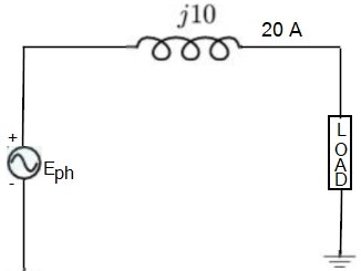
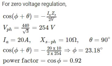
Ques 7. A star-connected 440V, the 50Hz alternator has per phase synchronous reactance of 10Ω. It supplies a balanced load current of 20A, as shown in the per-phase equivalent circuit diagram below. It is desirable to have a zero voltage regulation. The load power factor should be
0.82
0.62
0.50
0.92
Answer.4. 0.92
Explanation:
Ques8. The synchronous motor connected to an infinite bus takes power at a lag p.f. If its excitation is increased
Terminal Voltage increase
Load angle increase
Power factor Increase
None of the above
Answer.3.Power factor Increase
Explanation:
Synchronous Motor connected to infinite Bus
For constant power output, a synchronous motor can be made to operate at either a lagging power factor, unity power factor or leading power factor by varying the field excitation.
At normal excitation, the motor draws minimum armature current at unity power factor.
At under excitation the armature current increases and the power factor becomes lagging.
When the motor is overexcited it draws a current at the leading power factor.
An overexcited synchronous motor acts as a power factor correction device and is also known as a synchronous condenser. The variation of armature current and power factor as a function of field current is plotted to give a better insight.
We can state that an over-excited synchronous motor draws a leading power factor current from the mains. The synchronous motor, therefore, when over-excited, in addition to driving some load, will work as a capacitor or condenser. A capacitor draws a leading power factor current. An over-excited synchronous motor draws the leading power factor current from the mains.
An over-excited synchronous motor is also called a synchronous condenser. Synchronous motors are used as constant-speed drive motors. Over-excited synchronous motors are used to improve the power factor of electrical loads in industries. Generally, the motor is run on load, and by overexcitation, the system power factor is also improved.
Ques 9. The synchronous generator is connected to an infinite bus. If its excitation is increased
Supply reactive power
Absorb Reactive
Both 1 and 2
None of the above
Answer.1. Supply reactive power
Explanation:
The synchronous generators connected to the power system are generally over-excited in order to supply reactive power to the inductive power system loads. A synchronous generator operated without a torque input or load, but instead operated solely to supply reactive power is referred to as a synchronous condenser.
Synchronous Generator connected to an infinite bus
An infinite bus is a system that imposes its own voltage and frequency upon any apparatus connected to its terminals. Once connected to a large system (infinite bus), a synchronous generator becomes part of a network comprising hundreds of other generators that deliver power to thousands of loads. It is impossible, therefore, to specify the nature of the load (large or small, resistive or capacitive) connected to the terminals of this particular generator.
Infinite bus -effect of varying the exciting current of synchronous generator
Immediately after we synchronize a generator and connect it to an infinite bus, the induced voltage Eo is equal to, and in phase with, the terminal voltage E of the system. There is no difference of potential across the synchronous reactance and, consequently, the load current I is zero. Although the generator is connected to the system, it delivers no power; it is said to float on the line.
If we increase the excitation the synchronous generator voltage Vo will increase and the synchronous Reactance Xs will experience a difference of potential Vx.
Current (I) will circulate in the circuit
I = (Eo − E)/Xs
Where
E = Terminal voltage
Because the synchronous reactance is inductive, the current lags 90° behind E. The current is therefore 90° behind E, which means that the generator sees the system as if it were an inductive reactance.
Consequently, when we over-excite a synchronous generator, it supplies reactive power to the infinite bus. The reactive power increases as we raise the dc exciting current. Contrary to what we might expect, it is impossible to make a generator deliver active power by raising its excitätion.
If we increase the excitation the synchronous generator voltage Vo will increase and the synchronous Reactance Xs will experience a difference of potential Vx.
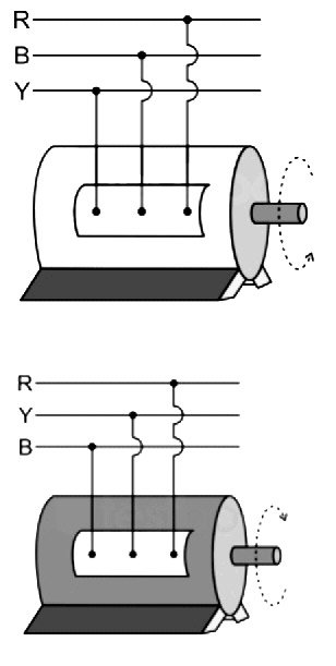
Ques 10. An alternator has a phase sequence of RYB for its phase voltage. In case the direction of rotation of the alternator is reversed, the phase sequence will become
YRB
YBR
RYB
RBY
Answer.4. RBY
Explanation:
Reversing an Alternator
The direction of rotation of an alternator is determined by its starting direction, as initiated by induction-motor action.
Thus, to reverse the direction of an alternator, it is necessary to first stop the motor and then reverse the phase sequence of the three-phase connections at the stator like an induction motor.
The direction of rotation of a 3-phase alternator can be changed by altering the phase sequence of the supply. I.e from RBY to RYB. Doing so will change the direction of rotation from clockwise to anticlockwise.
Reversing the current to the field windings will not affect the direction of rotation. If the current in the field winding is reversed the motor will run in the same direction. The field side will only slip through a pole-pitch due to the reversal of the polarities of the field poles.