
11. The characteristic impedance of a transmission line depends upon
- Shape of the conductor
- Conductivity of the material
- Surface treatment of the conductor
- Geometric configuration of the conductor
The surge impedance or characteristic impedance of a transmission line is given by
[katex]{Z_0} = \sqrt {\frac{{R\; + \;j\omega L}}{{G\; + \;j{\rm{\omega }}C}}}[/katex]
R = Resistance per unit length
L = Inductance per unit length
G = Conductance of dielectric per unit length
C = Capacitance per unit length.
Characteristic Impedance The characteristic impedance of a transmission line is determined by its geometry and the properties of the material through which the electromagnetic energy of the line flows.
12. Sheaths are used in underground cables to
- Protect the cable from moisture
- Provide mechanical strength
- Provide proper insulation
- All of the above
The underground cable is required to be protected from moisture, gases or other liquids of the soil and atmosphere. Therefore, the metallic sheath of aluminum, or lead, or alloy is used over the insulation for protection. A metal sheath is essential because no organic material is adequately moisture resistant. The main advantages of the lead sheath include easy-to-make, high-corrosion resistance, high flexibility, etc.
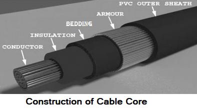
Recently, aluminum is also used as a sheath because of its low weight, low cost, ease to manufacture, and higher mechanical strength compared to the lead alloy. Aluminum eliminates the use of armor usually required in lead sheath cables. The aluminum sheath can withstand the required gas pressure Without reinforcement.
13. A short transmission line is having series impedance Z = 0.07 + j 0.12 p.u. If the transmission line is operating under full load at leading p.f., what will be the possible voltage regulation of the transmission line?
- 10%
- 0%
- 5%
- 20%
Voltage regulation:- When a transmission line is carrying current, there is a voltage drop in the line due to resistance and inductance of the line. The result is that the receiving end voltage (VR) of the line is generally less than the sending end voltage (Vs). This voltage drop (Vs − VR) in the line is expressed as a percentage of receiving end voltage VR and is called voltage regulation.
The difference in voltage at the receiving end of a transmission line between conditions of no-load and full-load is called voltage regulation and is expressed as a percentage of the receiving end voltage. Mathematically,
% Voltage regulation = (Vs − VR) ⁄ VR × 100
Obviously, it is desirable that the voltage regulation of a transmission line should be low i.e., the increase in load current should make very little difference in the receiving end voltage. In the transmission line, the voltage regulation is negative whenever the receiving end voltage VR is Greater than the sending end voltage.
The regulation will depend upon the power factor of the load. If the power factor is lagging, the voltage at the sending end is more than that at the receiving end. Hence, voltage regulation is positive. On the other hand, if the power factor is leading, the voltage at the sending end will be somewhat less than that at the receiving end. In that case, the regulation is negative.
The voltage regulation of a line is dependent on the load power factor. Voltage regulation improves(ΔV decreases) as the power factor of a lagging load is increased and it may become zero at a leading power factor. The inclusion of shunt capacitance at the receiving end for a heavily loaded line improves the receiving end voltage magnitude as well as receiving end p.f. and hence improves voltage regulation.
14. The insulation strength of an EHV transmission line is mainly governed by
- Harmonics
- Load power factor
- Switching overvoltage
- Corona
Switching Surges Switching surges can occur during the operation of circuit breaker and line switch opening (tripping) and closing at the same substation. In general, switching surges occur in the vicinity of non-self-restoring insulation equipment such as generators, transformers, breakers, cables, etc. Overvoltages caused by switching surges is a concern since they can damage insulation or cause insulation flashover. Damage and flashovers often lead to power system outages which is highly undesirable. The amplitude of a typical switching surge is about 1.5 pu with a duration of about one power frequency cycle.
Switching overvoltages do not cause flashovers to the same extent as caused by lightning. The frequency, point of occurrence, amplitude, and characteristics govern the selection of equipment, insulation level, and economical design. The switching surges gain more importance as the system voltage rises and in extra-high voltage (EHV) networks, it is the switching surges that are of primary importance in insulation coordination.
The switching surges have, generally, a power frequency and a transient component, which bear a certain relation to each other and maybe of equal amplitude in the absence of damping. The nonsimultaneous closing of breaker poles can increase the transient component. The EHV installations are primarily concerned with the stresses imposed on the insulation by switching surges and the coordination of the insulation is based upon these values. To lower the costs, it is desirable to reduce the insulation levels at high voltages. On the transmission line towers, the flashover voltage cannot be allowed to increase along with service voltage, as beyond a certain point the electrical strength of air gaps can no longer be economically increased by increasing the clearances. Thus, while the external lightning voltages are limited, the switching overvoltages become of primary concern.
15. At the terminal of a 3ϕ, 6.6 kV, 10 MVA alternator, a load R = 200 Ω is connected between two phases, and other phase is kept open. The sequence impedance of the alternator is Z1 = Z2 = j 5Ω and Z0 = j2Ω. What is the current through the load resistance?
- 32 A
- 23 A
- 16 A
- 8 A
This is the case of the line-to-line fault.
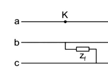
Ia = 0 (∵ open circuited)
Given:-
V = 6.6 kV
Z1 = Z2 = j5Ω
Zf = 200 Ω
Z0 = j2Ω
In a double line fault, the fault current is given by
[katex]I=\frac{\sqrt{3}V}{{{Z}_{1}}+{{Z}_{2}}+{{Z}_{f}}}[/katex]
[katex]I=\frac{\sqrt{3}V}{{{Z}_{1}}+{{Z}_{2}}+{{Z}_{f}}}=\frac{\sqrt{3}\times \frac{6.6}{\sqrt{3}}}{j5+j5+200}=\frac{6600}{200+j10}=32.9~A[/katex]
16. In the load flow analysis, Jacobian is represented as
[katex]\left[ {\begin{array}{*{20}{c}} H&N\\ M&L \end{array}} \right][/katex]
For decoupled load flow analysis, the assumptions made are
- B. H = 0; L = 0
- A. M = 0; L = 0
- D. H = 0; N = 0
- C. M = 0; N = 0
- Active power P is closely associated with power angle δ but it is less associated with bus voltage magnitude.
- An important characteristic of any practical electric power transmission system operating in steady-state is the strong interdependence between real powers and bus voltages angles and between reactive powers and voltage magnitudes. This interesting property of weak coupling between P- δ and Q-V variables gave the necessary motivation in developing the Fast Decoupled Load Flow, in which P- δ and Q-V problems are solved separately.
[katex]\left[ {\begin{array}{*{20}{c}} {\Delta P}\\ {\Delta Q} \end{array}} \right] = \left[ {\begin{array}{*{20}{c}} H&0\\ 0&L \end{array}} \right]\left[ {\begin{array}{*{20}{c}} {\Delta \delta }\\ {\Delta V} \end{array}} \right][/katex]
∆P = H.∆δ
∆Q = L.∆V
P is taken independent of V and Q is taken Independent of angle δ and thus those Jacobian elements are taken as zero.
17. In thyrite lightning arrester, on doubling the voltage the current increases to ______.
- 4 times
- 2 times
- 3 times
- 12.6 times
Thyrite Lightning Arrester
Thyrite is a mixture of a certain type of clay and carborundum. It has a non-linear property which at lower voltages acts as a non-conducting or insulating material and at higher voltages acts as a good conductor. The resistance offered by thyrite is voltage dependent. Whenever the voltage is doubled, the resistance decreases so as to pass more current through it. Hence, during a lightning surge, it allows the current through it to the earth. Once the surge has passed away, the thyrite regains its original resistance value at normal voltages without any permanent chemical changes. The basic cells of thyrite are used inside this type of lightning Arrester.
A thyrite lightning arrester consists of a number of discs stacked one above the other and electrically in series with air gaps in the series-gap unit. The discs and series-gap units are assembled inside a wet-process porcelain container. At the top and bottom, there are two aluminum castings. These castings are cemented to the porcelain container. The discs are kept in position by the spring underneath the top cap casting. The cap of the casting is connected to the line by a terminal at the top. The bottom case is connected to earth.
During the surge, the gap spark-over and the thyrite discs offer relatively low resistance to the flow of surge current. After the surge disappears, the discs regain their original high resistance and the series gap together with this high resistance do not allow any flow of current under the normal operating conditions.
Thyrite is used widely in lightning arresters. It does not follow Ohm’s law, for each time the voltage is doubled the current increases 12.6 times. This means the resistance decreases as the current and voltage increase
18. In transmission lines ________ loss is mainly dependent on the supply frequency.
- Core Loss
- Corona Loss
- Copper Loss
- Resistive Loss
Corona
It can be noticed that near the overhead lines there exists a hissing noise and sometimes a faint violet glow. The effect due to which such phenomenon exists surrounding the overhead lines is called corona effect.If the voltage applied exceeds a particular limiting value then the air surrounding the conductors gets ionized.The faint violet glow is even between the two parallel polished conductors and can be seen all along the length of the conductors. At the rough points, it appears a little bit brighter. In case of d.c. voltage reddish beads are formed near negative conductor while smoother bluish-white uniform glow is formed near the positive conductor. The hissing noise can be easily heard while the formation of ozone gas can be detected from its odour.
Thus the phenomenon of hissing noise, faint violet glow, and production of ozone gas surrounding the Overhead lines, due to ionization of air is called corona.
Corona loss is given by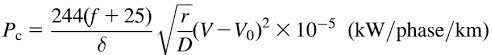
Where, f = Supply frequency
δ = Air density factor
r = Radius of the conductor
D = Distance between the conductors
V = Operating voltage of the transmission line
Vo = Critical disruptive voltage
Corona loss can be minimized by controlling the following factors:
- The frequency of supply: Corona loss increases as the supply frequency increases.
- The radius of the conductors: Generally corona loss increases when decreasing the radius of the conductor. In order to prevent this, bundled or hollow large diameter conductors must be used.
- The distance between the two conductors: To prevent corona spacing between the conductors must be increased.
- Air Pressure: In hilly areas, the corona effect is more dominant due to reduced pressure.
- Using Smooth conductor: Since corona loss is higher at sharp corners of the conductors, due to the presence of the highly non-uniform field, increasing the conductor radius as a whole can reduce the corona effect significantly. More the imperfections on the conductor surface more will be Corona.
19. A dc 3-wire distributor system requires how much of copper as compared with a dc 2-wire distributor system?
- 33.33%
- 66.66%
- 22.22%
- 5/16
- For the same conductor length, the same amount of power, same losses and same maximum voltage to earth, 3 wire DC system requires minimum conductor area
- For transmitting the same amount of power at the same voltage, a three-phase transmission line requires less conductor material than a single-phase line; The three-phase transmission system is so cheaper
- For a given amount of power transmitted through a system, the three-phase system requires conductors with a smaller cross-sectional area; This means a saving of copper and thus the original installation costs are less
Conductor Material required in the Distribution system
System |
Same maximum voltage to earth |
Same maximum voltage between conductors |
| DC system: Two-wire | 1 | 1 |
| DC: Two-wire mid-point earthed | 0.25 | 1 |
| DC: 3 wire | 0.3125 = 5 / 16 | 1.25 |
| Single-phase: 2 wire | 2/cos2ϕ | 2/cos2ϕ |
| Single-phase: 2 wire mid-point earthed | 0.5/cos2ϕ | 2/cos2ϕ |
| Single-phase: 3 wire | 0.625/cos2ϕ | 2.5/cos2ϕ |
| 2-phase: 4 wire | 0.5/cos2ϕ | 2/cos2ϕ |
| 2-phase: 3 wire | 1.457/cos2ϕ | 2.914/cos2ϕ |
| 3 phase, 3 wire | 0.5/cos2ϕ | 1.5/cos2ϕ |
| 3 phase, 4 wire | 0.583/cos2ϕ | 1.75/cos2ϕ |
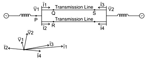
20. A sustained three-phase fault occurs in the power system shown in the figure. The current and voltage phasors during the fault (on a common reference), after the natural transients have died down, are also shown. Where is the fault located?
- Point S
- Point Q
- Point R
- Point P
As shown in the phasor diagram
- The Transmission line Current I2 & I4 have a phase difference of 180°. So that they cancel out each other. Hence the transmission line is working fine
- In the other transmission line the magnitude of the current I1 is more than current I3. Also I1 is more lagging than I3. So the fault is located at point Q.
FOR TRANSMISSION AND DISTRIBUTION SYSTEM MCQ CLICK HERE
FOR DC MOTOR MCQ CLICK HERE
FOR 1-Φ INDUCTION MOTOR MCQ CLICK HERE
FOR 3-Φ INDUCTION MOTOR MCQ CLICK HERE
FOR SYNCHRONOUS GENERATOR OR ALTERNATOR MCQ CLICK HERE
FOR SYNCHRONOUS MOTOR MCQ CLICK HERE
FOR DC MOTOR MCQ CLICK HERE
FOR DC GENERATOR MCQ CLICK HERE
FOR POWER SYSTEM MCQ CLICK HERE
FOR TRANSFORMER MCQ CLICK HERE
FOR BASIC ELECTRICAL MCQ CLICK HERE
FOR CONTROL SYSTEM MCQ CLICK HERE
