
1) In distributed systems, the transportation delays are detrimental to stability due to which of the following reasons?
- Attenuation
- Phase lag
- Attenuation & Phase Lag
- Transient
Time Delay:- Perhaps the most common explanation of a decision-making failure is something of the sort “by the time we got the information, it was too late,” or its more positive version “given the information we had at the time, our decision was correct.” The main point of such an argument is that the information necessary to make the right decision arrived too late. Time delays between an event’s occurrence and corrective action can cause instabilities. The main cause of time delay is
Transportation Delay:- Typically, transport delays occur when sensors are downstream from the point of control influence, thereby introducing a delay in the information received by the controller. Transportation delays are detrimental to stability because they provide no attenuation and produce a phase lag that increases linearly with frequency. The transportation lag is the delay between the time an input signal is applied to a system and the time the system reacts to that input signal. Transportation lags are common in industrial applications. They are often called “dead time”.
There are essentially two types of delays or time buffers required to maintain a controlled transportation network:
Attenuation:- Batching of items into containers, trailers, or railcars necessary to achieve an efficient network. This is also referred to as scheduling or attenuation. It would be economically impossible to transport each item in its own truck or train to its destination. Items have to be grouped until a departure can be scheduled where the vehicle will be reasonably full.
Phase Lag:- Another type of delay that is necessary to establish control is slack time or Phase Lag. Phase Lag is designed to absorb schedule variations that may happen as a result of unplanned changes such as breakdown, weather delays, etc. Without slack time, transportation networks may be drawn into chaos, and items transported may not meet their schedule requirements.
2 If the positive, negative, and zero-sequence reactance of an element of a power system is 0.3, 0.3, and 0.8 p.u. respectively, then the element would be a?
- Transmission line
- Synchronous generator
- Synchronous motor
- Static load
⇒ For transmission line,
Negative sequence component = positive sequence component
Zero sequence component > positive sequence component, Negative sequence component
Z0 > Z1 = Z2
⇒ For Synchronous Machine
Negative sequence component = positive sequence component
Zero sequence component < positive sequence component, Negative sequence component
Z0 < Z1 = Z2
⇒ For the transformer,
Negative sequence component = positive sequence component = zero sequence component
Z0 = Z1 = Z2
In the above question, the given data is
Z1 = 0.3 pu
Z2 = 0.3 pu
Z0 = 0.8 pu
⇒ Z0 > Z1 = Z2
Therefore, the element is a transmission line.
3 A 66 kV system has a string insulator having three discs and the earth to disc capacitance ratio of 0.10 The string efficiency will. Be:
-
75.56%
- 87.43%
-
66.93%
-
55.45%
Voltage of disc nearest to conductor V₂ = V₁(1+K)
K = 0.1
V₂ = V₁(1+0.1) = 1.1V₁
V₃ = V₂ + (V₁ + V₂) K = 1.1V₁ + 2.1V₁(0.1) = 1.31V₁
V₄ = V₃ + (V₁ + V₂ + V₃)K = 1.31V₁ + 3.41V₁ × 0.1 = 1.651V₁
V₅ = V₄ + (V₁ + V₂ + V₃ + V₄)K = 1.651V₁ + (5.061V₁) × 0.1 = 2.1571V₁
String Efficiency = (V₁ + V₂ + V₃ + V₄ + V₅)/(n V₅) × 100
n = number of disc = 5
=> String Efficiency = (V₁ + 1.1V₁ + 1.31V₁ + 1.651V₁ + 2.1571V₁)/(5 × 2.1571V₁) × 100
= 7.2181V₁ / 10.7855 × 100
= 66.93 %
≈ 67 %
4 Making capacity of Circuit breaker is
- Lesser than the asymmetrical breaking capacity
- Greater than the asymmetrical breaking capacity
- Equal to the symmetrical breaking capacity
- Equal to the asymmetrical breaking capacity
Making capacity used the peak value of current while breaking capacity work on the RMS value of current that’s why making capacity is more than breaking capacity. Let’s explain in detail.
Breaking capacity of Circuit Breaker
When the breaker is closed and a fault occurs then it closes in the transient state(in transient state DC offset become zero) so the current capacity at this instant is only the RMS value of current(symmetrical component)in the transient state which is also called breaking capacity of the breaker.i.e
Breaking capacity=rms value of breaking current in the transient state.
Making Capacity Of Circuit Breaker
Now when the breaker is going to be closed and at that time fault occurs then it will close sub-transient state and the current-carrying capacity at this instant contains RMS value of current (the symmetrical component in the transient state) and the DC offset current in the sub-transient state which is also called Making capacity of the breaker at the sub-transient period amount of arc produce will be very high. Thus making capacity is very high.i.e
Making Capacity = DC offset current + RMS value of breaking current in a transient state
Making capacity = 2.55 × Breaking capacity
Thus Making capacity > Breaking Capacity
5 Plant use factor is
- Maximum demand/Connected load
- Number of units generated/(Plant capacity × number of hours plant operated)
- Average demand/plant capacity
- Average load/Maximum load
Plant capacity factor is the ratio of average demand to the maximum installed capacity of the station.
Plant capacity factor = Average demand ⁄ Max. Plant capacity
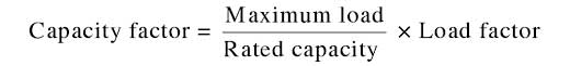
Capacity Factor
The capacity factor indicates the extent of use of the generating station. It is different from the load factor because of the reason that the rated capacity of each plant is always greater than the expected maximum load due to some reserve capacity. Thus
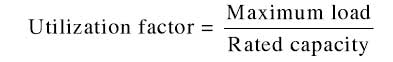
Utilization Factor
It is defined as the ratio of maximum demand to the rated capacity of the plant
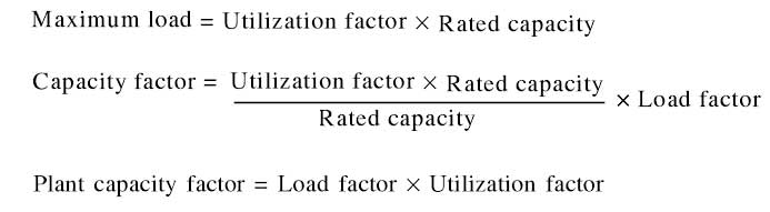
Hence plant capacity factor is also the product of the load factor and the utilization factor.
Plant use factor — It is the ratio of kWh generated to the product of plant capacity and the number of hours for which the plant was in operation, i.e.,

6 The problems associated with the use of a series capacitor for power factor improvement is listed in the options. Which option is not true?
- Series compensated line has a tendency to cause series resonance, called sub synchronous resonance of frequencies lower than power frequencies
- The effect of a series capacitor is more than that of a shunt capacitor in power factor improvement
- Switching-in of an unloaded transformer may develop Ferro resonance
- Series capacitor develops high recovery voltage across the circuit breaker contacts
Improving the power factor means reducing the phase difference between voltage and current. So capacitor or bank of capacitor installed in parallel to load provides reactive power for function, the effect of a series capacitor is less in comparison to that of the parallel capacitor.
Shunt Capacitive Compensation:– This method is used to improve the power factor. Whenever an inductive load is connected to the transmission line, the power factor lags because of the lagging load current. To compensate, a shunt capacitor is connected, which draws current leading to the source voltage. The net result is an improvement in the power factor.
Series Compensation:- Series compensation is a well-established technology that is primarily used to reduce transfer reactances, most notably in bulk transmission lines. The result is a significant increase in the transient and voltage stability in transmission systems. In the `series compensation, the FACTS is connected in series with the power line/system. It works as a controllable voltage source. It is of two types (as in case of the shunt compensation), namely (i) series reactors and (ii) series capacitors.
During compensation by series capacitors following problems are occurred:
- Switching-in of an unloaded transformer may develop Ferro-resonance.
- A Series capacitor develops high recovery voltage across the circuit breaker contacts.
- A series compensated line has a tendency to cause series resonance, called subsynchronous resonance of frequencies lower than power frequencies.
Important Points:
- Series reactors are used as current limiting reactors to increase the impedance of a system. They are also used to limit the starting currents of synchronous electric motors and to compensate for reactive power to improve the transmission capacity of power lines.
- A shunt reactor is an absorber of reactive power, thus increasing the energy efficiency of the system
7 The per-unit parameters for a 1000 MVA machine on its base are M = 40 p.u. and H = 5 p.u. The per-unit values of M and H on 100 MVA base of
- 4 p.u., 50 p.u.
- 40 p.u., 5 p.u.
- 40 p.u., 50 p.u.
- 4 p.u., 5 p.u.
Given Data
M = Angular momentum = 40 p.u.
H = Inertia constant = 5 p.u.
S1 = Rating of the machine = 1000 MVA
S2 = 100 MVA
The relation between M and H is
[katex]\begin{array}{l}M = \frac{{SH}}{{\pi f}}\\or\\H \propto \frac{1}{s}\\\therefore \frac{{{H_2}}}{{{H_1}}} = \frac{{{S_1}}}{{{S_2}}}\end{array}[/katex]
Also
⇒ M ∝ S
From the above equation
M2 = M1S2 / S1 = 40 × 100 / 1000 = 4 p.u
H2 = H1S1 / S2 = 5 × 1000/100 = 50 p.u
The per-unit values of M and H on 100 MVA base is 4 p.u & 50 p.u.
8 An overhead line with surge impedance of 400 Ω is terminated through a resistance R. A surge traveling over the line does not suffer any reflection at the junction if the value of R is:
- 200 Ω
- 20 Ω
- 40 Ω
- 400 Ω
- When the receiving-end voltage and current are numerically equal to the corresponding sending-end values so that there is no voltage drop on load. Such a line is called a tuned line
- The tuned line or loss-free overhead transmission line is terminated through a resistance equal to surge Impedance of the line, there will be no reflection of traveling wave hence the value of R is 400 Ω.
- When the line is terminated in its characteristic load impedance, i.e., Z1 = Zo, the reflected wave is zero. Such a line is called an infinite line and the incident wave cannot distinguish between termination and the continuation of the line.
- The reflection of voltage and current is zero for the tuned power line.
- The transmission line work on the unity power factor.
- A method of tuning power lines uses series capacitors to cancel the effect of the line inductance and shunt inductors to neutralize line capacitance. A long line is divided into several sections which are individually tuned. However, so far the practical method of improving line regulation and power transfer capacity is to add series capacitors to reduce line inductance; shunt capacitors under heavy load conditions, and shunt inductors under light or no-load conditions.
- The load impedance is equal to the surge impedance of the line. Surge Impedance for the transmission line is about 400 ohms it is around 40 ohms for underground cables.
9 How much power is developed when a hydropower plant operates under an effective head of 20 m and a discharge of 30 m3/sec?
- 3.86 MW
- 4.75 MW
- 5. 88 MW
- 6.23 MW
Power developed in a hydro-power plant is given by
P = ρ × Q × g × H
Where
H = falling height, head (m)
Q = water discharge (m3/s)
g = acceleration of gravity (9.81 m/s2)
ρ = density (kg/m3) (~ 1000 kg/m3 for water)
Given Data
H = 20 m
Q = 30 = m3/sec
∴ P = 1000 × 30 × 9.8 × 20
= 58.8 × 105 = 5.88 MW
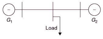
10 A load center is at an equidistant from the two thermal generating stations G1 and G2 as shown in the figure. The fuel cost characteristics of the generating stations are given by
F1 = a + bP1 + CP12 Rs/hour
F2 = a + bP2 + CP22 Rs/hour
Where P1 and P2 are the generations in MW of G1 and G2 respectively. For most economic generation to meet 300 MW of Load, P1, and P2 respectively are
- 200, 100
- 150, 150
- 200, 200
- 100, 300
Given
⇒ F1 = a + bP1 + CP12 Rs/hour
dF1/dP1 = b + 2CP1
⇒ F2 = a + bP2 + CP22 Rs/hour
dF2/dP2 = b + 2CP2
For most economic generation
dF1/dP1 = dF2/dP2
b + 2CP1 = b + 4CP2
P1 = 2P2
Given P1 + P2 = 300
⇒ P1 = 200 MW, P2 = 100 MW
