Ques 11. An alternator has a phase sequence of RYB. In case the field current is reversed, the phase sequence will become
RBY
RYB
YRB
YBR
Answer.2. RYB
Explanation:
The direction of rotation of the synchronous generator is determined by its starting direction, as initiated by induction motor action.
Thus, to reverse the direction of a 3 phase synchronous generator, it is necessary to first stop the motor and then reverse the phase sequence of the 3 phase connections at the stator.
REVERSING THE CURRENT TO FIELD WINDINGS WILL NOT AFFECT THE DIRECTION OF ROTATION.
Ques 12. The gauss-Seidel iterative method can be used for solving a set of
Linear differential equations only
The linear algebraic equation only
Both linear and nonlinear algebraic equations
Both linear and nonlinear differential equations
Answer.2. The linear algebraic equation only
Explanation:
The advantages of the Gauss-Seidel method are:-
A simple algebraic equation is used hence it requires less number of arithmetic operation to complete iteration and therefore the time required for each iteration is less
The need for computer memory is less.
This method is most suitable for a small size networks.
Ques 13. The pure inductive circuit takes power (reactive) from the a.c. line when
Both applied voltage and the current rise
Applied voltage decreases but current Increases
Both applied voltage and current decrease
None of these
Ques 13. A square matrix is called singular if its
Determinant is zero
The determinant is infinity
Rank is unity
None of the above
Answer.1. Determinant is zero
Explanation:
In linear algebra, an n-by-n square matrix A is called invertible (also nonsingular or nondegenerate) if there exists an n-by-n square matrix B such that AB = BA = In
A square matrix that is not invertible is called singular or degenerate. A square matrix is singular if and only if its determinant is 0. Singular matrices are rare in the sense that a square matrix randomly selected from a continuous uniform distribution on its entries will almost never be singular.
Ques 14. In load flow analysis, the load connected to a bus is represented as
Constant impedance connected to the bus
Voltage and frequency-dependent source at the bus
Constant real and reactive drawn from the bus
Constant current is drawn from the bus
Answer.3. Constant current is drawn from the bus
Explanation:
Load flow studies determine if system voltages remain within specified limits under normal or emergency operating conditions and whether equipment such as transformers and conductors are overloaded.
A load flow study is the steady-state analysis of the power system network.
To solve non-linear algebraic equations it is important to have fast, efficient, and accurate numerical algorithms.
The output of the load flow analysis is the voltage and phase angle, real and reactive power (both sides in each line), line losses, and slack bus power.
Ques 15. If transformer frequency is changed from 50 Hz to 60 Hz the ratio of eddy current loss 50 Hz to 60 Hz, at constant voltage will be
1
2
5/6
25/36
Answer.4. 25/36
Explanation:
Eddy current losses are given as Pc ∝ Ke B2m f2
Ques16. When a d.c source is switched is purely inductive, the current response is
Increase exponentially and reach a constant value
Exponentially decaying curve
A straight line passing through the origin
A straight line offset from the origin
Answer.1.Increase exponentially and reach a constant value
Explanation:
When an inductor is connected to the circuit and the supply is turned on, initially, for a very short time, there will be an open circuit. Inductors will develop a magnetic field during this period. After that, the current will increase exponentially (1 – e(-t)) and reach a constant value.
The current will be maximum and the inductor will behave like a short circuit.
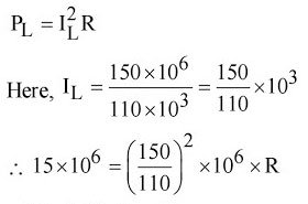
Ques 17. A 100 km long transmission line is loaded at 110 kV. If the loss of line is 5 MW and the load is 150 MVA, the resistance of the line is
8.06 ohms per phase
0.806 ohms per phase
0.0806 ohms per phase
80.6 ohms per phase
Answer.1. 8.06 ohms per phase
Explanation:
The power loss in the line is given as PL =IL2R
Ques 18. At a particular unbalanced node, the real powers specified are leaving the node 20 MW, 25 MW entering the node 60 MW, 30 MW then the balanced power will be
30 MW leaving the node
45 MW leaving the node
45 MW entering the node
22.5 MW entering and 22.5 MW leaving the node
Answer.3. 45 MW entering the node
Explanation:
According to Kirchhoff’s current law (KCL) at any node (junction) in an electrical circuit, the sum of currents flowing into that node is equal to the sum of currents flowing out of that node.
Sum of power entering the node 60 + 30 =90 MW Sum of power leaving the node 20 + 25 = 45
To make the power flow balanced sum of power entering the node must be equal to the sum of power leaving the node. Hence the sum of power entering the node must be equal to 45 MW.
Ques 19. Series capacitive compensation on EHV transmission lines is used to
Reduce the line loading
Improve the stability of the system
Reduce the voltage profile
Improve the protection of the line
Answer.2. Improve the stability of the system
Explanation:
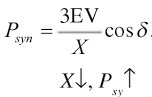
The series capacitive compensation decrease the overall effective series transmission impedance from the sending end to the receiving end. Hence it increases the power system stability.
Synchronising power Psyn is given as
The advantages of series compensation are
Increase transmission capability
Increase power corridor angular stability
Damp oscillation
Enhance power-sharing between parallel line
Ques 20. The transmission line feeding power on either side of the main transmission line is called as
Primary distribution
Primary transmission
Secondary distribution
Secondary transmission
Answer.4.Secondary transmission
Explanation:
Secondary Transmission
The primary transmission line continues via transmission towers till the receiving stations.
At the receiving stations, the voltage level is reduced to 22 kV or 33 kV using via the step-down transformer.
Then at the reduced voltage level of 22 kV or 33 kV, the power is then transmitted to various substations using overhead 3 phase 3 wire system.
The conductors used for the Secondary transmission are called feeders.