
11 A 100 km transmission line is designed for a nominal voltage of 132 kV and consists of one conductor per phase. The line reactance is 0.726 W/km. The static transmission capacity, in megawatts, would be:
- 145
- 360
- 240
- 140
Total line reactance X = 0.726 × 100 = 72.6 Ω
Nominal voltage = 132 kV
The static transmission capacity = V2/X
= 1322/72.6 = 240 MW
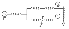
12 The equal-area criterion is applied for the determination of the transient stability limit of the power system shown in the figure below. For sudden tripping of line 1 which of the following diagrams is correct?
- Any of the above
The equal-area criterion is a simple graphical method for determining whether a one-machine infinite bus system will remain stable. It provides a useful representation of the factors that affect stability. In practical systems, it may also be used to obtain a first approximation of the stability limit.
The main cause for the study of transient stability problems in a system are
- Sudden changes in Load
- The switching of one of the lines causes a change in the reactance of the system and hence a change in load conditions.
- Sudden fault on the system which causes a reduction in output, requiring arrangement for clearance of fault quickly, and study of
an after-fault condition that may cause part of the system outage.
Consider a generator supplying power to an infinite bus through a double circuit line as shown in Fig.
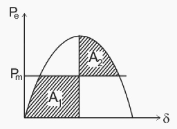
Let the system be operating with a mechanical input Pm, at a steady-state operating angle δo, as indicated by point ‘a’ on Fig,
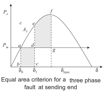
If now a three-phase fault occurs at the sending end bus (point F1 in Fig.), the electrical output of the generator reduces to zero and the operating point shifts to b. The generator is subject to acceleration and the rotor angle moves along bc. Let the fault be cleared at point c, at a time te called clearing time, corresponding to an angle called the clearing angle. The power angle curve is now the same as the pre-fault curve and the operating point shifts to e.
The rotor is now subject to deceleration and the rotor angle moves along ef till at f, when A2 = A1, the rotor runs at synchronous speed and the rotor angle is δmax. The rotor now again moves along fe in the reverse direction, since it is still subject to deceleration. Due to damping, the machine oscillates around δo for a few swings and then settles down at point a.
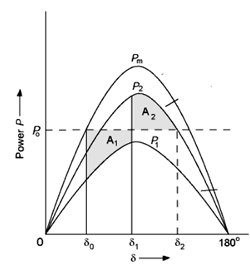
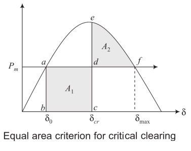
As the clearing time tc increases, so does δ1 , causing an increase in area A1, till a critical case is reached beyond which A3 < A1. The critical case is shown in Fig.. Here, the rotor should reach a synchronous speed at f. Else, if it moves beyond f, with a positive velocity deviation, the acceleration will cause the velocity deviation to increase further and stability is lost. This maximum clearing time is called the critical clearing time (tcr) and the angle at the time of clearing is called the critical clearing angle (δcr). If the fault persists longer than rm, the system loses stability.
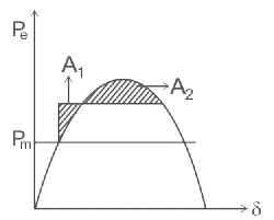
- With the sudden fault occurrence in a system, the power of the system reduced.
- As the fault is cleared by tripping one of the transmission lines the post-fault curve will not be the same as the pre-fault curve.
- If a three-phase fault occurs at the generator terminals or the bus-bar terminal, the power during fault drops to zero. Here the fault occurs in the middle of one of the transmission lines therefore the power during fault does not drop to zero.
13 The insulation resistance of a cable of length 20 km is 2 MΩ. What will be the insulation resistance of the same cable but for a length of 200 km?
- 12 MΩ
- 20 MΩ
- 0.2 MΩ
- 40 MΩ
Insulation resistance is inversely proportional to length of the cable by
[katex]{R_i} = \frac{\rho }{{2\pi l}}ln\frac{{{r_2}}}{{{r_1}}}[/katex]
Where ρ = specific resistance of the insulation material
l = length of cable
r2 = outer radius of cable
r1 = radius of conductor
Given data
Ri = 2 MΩ
l1 = 20 Km
Ri2 = ? MΩ
l2 = 200 Km
Ri/Ri2 = l2/l1
2/Ri2 = 200/20
Ri2 = 0.2 MΩ
14 HRC fuse has a rupturing capacity of capability _________ in comparison with a circuit breaker
- Equal
- Greater than
- Less than
- Can’t say
H.R.C Fuse
HRC fuses are used for high current applications. The HRC fuse is a high-grade ceramic barrel containing the fuse element. The barrel is filled with silica powder (sand), which helps to quench the arc produced when the element melts. The barrel is able to withstand the shocks which occur when a high fault current is interrupted. The fuse elements are in parts connected in the middle by bridges which have a very precise melting point of about 230° C. With a specific current, the temperature rises and the bridge melts producing a break in the circuit. The metal vapor diffuses with silica powder. When the fuse is blown off, the entire fuse unit (fuse with fuse carrier) is replaced. The HRC fuses are expensive. They are manufactured with current ratings of up to 1250 A.
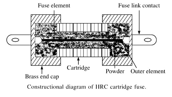
Rupturing capacity of a circuit breaker means the maximum power a circuit breaker can interrupt under fault. It is usually expressed in Mega Volt Ampere (MVA) and it is then the product of the rated breaking current in kilo amperes and rated voltage expressed in kilovolts.
For interrupting devices under conditions of short circuit, modern high-rupturing-capacity (HRC) fuses are used in medium-voltage installations (range 400 to 600 V). These types of fuses can easily interrupt fault currents up to 40 km. The superiority of HRC fuses lies in the fact that they limit the fault current to a value smaller than the peak in the first half cycle of the short circuit. Thus, the fault is cleared in less than one-half cycle. They occupy less space and are less expensive than the circuit breakers. The only disadvantage is that they need replacement, once the fuses operate. High-rupturing-capacity fuses basically consist of a ceramic body containing one or two specially designed fuse elements that are connected to metal-end caps. After the fuses blow, the body is filled with a powder—-usually quartz—which acts as an insulating material thus disconnecting the circuit.
- HRC fuse has the rupturing capacity of capability less than a circuit breaker
- When compared to other circuit interrupters of the same capacity HRC fuses are the cheaper ones.
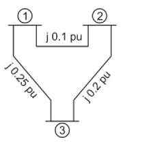
15 A single line diagram of a power system is shown in the figure. The per-unit values of line impedances are given. The sum of diagonal elements of YBUS matrix is
- −j0.35 pu
- j1.1 pu
- −j0.38 pu
- j0.38 pu
Z12 = j0.10 pu ⇒ y12 = -j10 pu
Z13 = j0.25 pu ⇒ y13 = -j4 pu
Z23 = j0.2 pu ⇒ y23 = -j5 pu
Y11 = y12 + y13 = -j10 + (-j4) = -j14 pu
Y12 = y12 + y23 = -j10 + (-j5) = -j15 pu
Y13 = y13 + y23 = -j4 + (-j5) = -j9 pu
Sum of diagonal elements = -j14 – j15 – j9
= -j38 pu
16. The most efficient power plant is ______
- Hydro electric power plant
- Coal- based steam power plant
- Nuclear power plant
- Diesel engine power plant
The most efficient power plant is the Hydroelectric power plant.
“Hydro” is a Greek word meaning water. “Hydropower” means the power in the moving water, and hydroelectric is the process by which hydropower is converted into electricity.
The overall plant efficiency, including generator, turbine, transformer, and associated equipment including Station services, but not penstock or open channel losses, usually used for estimating and power studies is as follows;
Storage dam plant 80% maximum
Run-of-river plant 75%
Equipment efficiencies are assumed to be at least as good as.
Generator 96%
Peak efficiency of turbine = 90%
Full load turbine efficiency (design head) = 85%
The efficiency of the hydroelectric plant is in the range of 85 to 90 %.
Wind turbines have an overall conversion efficiency of 30 % to 40 %.
The geothermal conversion efficiency is 30 to 35%
Solar thermal systems efficiency is up to 20 %.
17. The conductors of 1.6 km long, 3-phase, 3.3 kV overhead lines are in horizontal formation with 762 mm between centers. The effective diameter of the conductors is 3.5 mm. The equivalent spacing (in mm) is
- 360
- 400
- 780
- 960
For the conductors spaced horizontally, the equivalent distance is,
[katex]{D_{eq}} = \sqrt[3]{{\left( {{d_{12}}{d_{23}}{d_{13}}} \right)}}[/katex]
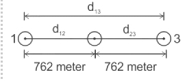
Distance between conductors is, 762mm
Therefore, d12 = d23 = 762 mm, d13 = 1524 mm
[katex]{D_{eq}} = \sqrt[3]{{\left( {762 \times 762 \times 1524} \right)}} = 960\;mm[/katex]
18 Ferranti effect states that under certain conditions, the sending end voltage is
- Less than receiving end voltage
- Equal to receiving end voltage
- Greater than receiving end voltage
- 2 time the sending end voltage
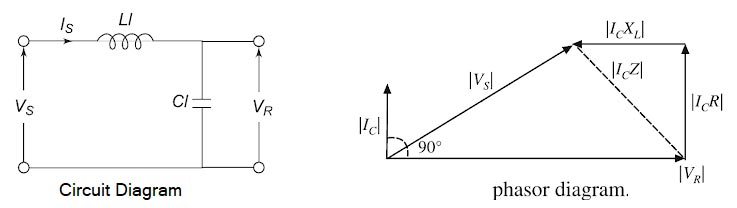
A long transmission line has a large capacitance. When a long line is operating under the no-load condition, the receiving-end voltage is greater than the sending end voltage. This is known as the Ferranti effect. This phenomenon can be explained by the following reasoning. It was first noticed by Ferranti on overhead lines supplying a lightly loaded network. Ferranti effect is due to the charging current of the line. The value of current at the sending end at no-load and normal operating voltage applied at the sending end is called the charging current. In the Ferranti effect, the receiving end voltage becomes greater than sending end voltage.
A simple explanation of the Ferranti effect can be given by approximating the distributed parameters of the line by lumped impedance as shown in Figure. Since usually, the capacitive reactance of the line is quite large as compared to the inductive reactance, under the no-load or lightly loaded condition, the line current is of leading pf. The phasor diagram is given below for this operating condition. The charging current produces a drop in the reactance of the line which is in phase opposition to the receiving-end voltage and hence the sending-end voltage becomes smaller than the receiving-end voltage.
Note:-
- The Ferranti Effect will be more pronounced the longer the line and the higher the voltage applied. The relative voltage rise is proportional to the square of the line length.
- The Ferranti effect is much more pronounced in underground cables, even in short lengths, because of their high capacitance.
19. HVDC Homo polar links uses
- Two conductors of positive and negative polarity
- Two conductors of negative polarity
- Two conductors of positive and negative polarity
- One conductor usually of negative polarity
The type of DC-link that is considered in HVDC application are
- Monopolar
- Bipolar
- Homopolar
Homopolar Link
- The homopolar link, whose configuration is shown in Figure has two or more conductors, all having the same polarity. Usually, negative polarity is preferred because it causes less radio interference due to corona.
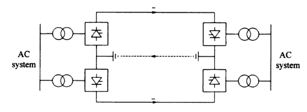
- The return path for such a system is through the ground. When there is a fault on one conductor, the entire converter is available for feeding the remaining conductor(s) which, having some overload capability, can carry more than the normal power.
- In contrast, for a bipolar scheme reconnection of the whole converter to one pole of the line is more complicated and usually not feasible.
- The homopolar configuration offers an advantage in this regard in situations where the continuous ground current is acceptable.
- The ground current can have side effects on gas or oil pipelines that lie within a few miles of the system electrodes. Pipelines act as conductors. for the ground current which can cause corrosion of the metal. Therefore, configurations using ground return may not always be acceptable.
20. Which of the following steps does not hold true for the steps involved in the Newton-Raphson method of load flow study?
- Use the estimated |V|(0) and δ(0) to calculate a total np number of injected reactive power Qcalc(0) and an equal number of reactive power mismatch ΔQ(0).
- Use the estimated |V|(0) and δ(0) to formulate the Jacobian matrix j(0).
- Choose initial values of the voltage magnitude |V|(0) for all np load buses and n-1 angles δ(0) of the voltages of all the buses except the slack bus
- Use the estimated |V|(0) and δ(0) to calculate a total n number of injected real power Pcalc(0) and an equal number of real power mismatch ΔP(0).
Newton Raphson Method is an iterative technique for solving a set of various nonlinear equations with an equal number of unknowns.
Let us assume that an n-bus power system contains a total number of np P-Q buses while the number of P-V (generator) buses be ng such that n = np + ng + 1.
Bus-1 is assumed to be the slack bus.
ALGORITHM FOR SOLVING THE POWER FLOW PROBLEM USING N-R METHOD
- Choose the initial values of the voltage magnitudes |V|(0) of all np load buses and n − 1 angles δ(0) of the voltages of all the buses except the slack bus.
- Use the estimated |V|(0) and δ(0) to calculate a total n − 1 number of injected real power Pcalc(0) and equal number of real power mismatch ΔP(0).
- Use the estimated |V|(0) and δ(0) to calculate a total np number of injected reactive power Qcalc(0) and equal number of reactive power mismatch ΔQ(0).
- Use the estimated |V|(0) and δ(0) to formulate the Jacobian matrix J(0).
- Check if all the mismatches are below a small number. Terminate the process if yes. Otherwise, go back to step-1 to start the next iteration
