
1. A fault in the transmission is highly severe from the point of view of RRRV if it is a
- Short line fault
- Long line fault
- Medium line fault
- All of the above
Fault in the transmission from the point of view of RRRV
- If the fault occurs immediately after the circuit breaker, the short-circuit current is large, while the maximum value of re-striking voltage, Em is small as length is small, the amplitude is thus quite low.
- if the fault is far from the circuit breaker, ‘the fault current is small and hence RRRV is small, although Em is large.
- When the fault is at a short distance from the circuit breaker, both RRRV and Em have considerable value and hence the possibility of failure is maximum. Such a fault is known as a kilometric fault or short-line fault.
Consider the opening of a circuit breaker under fault conditions shown in the figure. Before the current interruption, the capacitance C is short-circuited by the fault and the short-circuit current through the breaker is limited by inductance L of the system only. Consequently, the short-circuit current will lag the voltage by 90° where i represents the short-circuit current and ea represents the arc voltage.
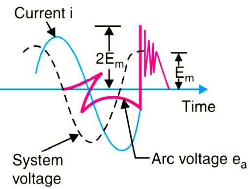
When the contacts are opened and the arc finally extinguishes at some current zero, the generator voltage e is suddenly applied to the inductance and capacitance in series. This L-C combination forms an oscillatory circuit and produces a transient of frequency
fn = 1/2π√LC
which appears across the capacitor C and hence across the contacts of the circuit breaker. This transient voltage, as already noted, is known as re-striking voltage and may reach an instantaneous peak value twice the peak phase-neutral voltage i.e. 2 Em. The system losses cause the oscillations to decay fairly rapidly but the initial overshoot increases the possibility of re-striking the arc. It is the rate of rise of re-striking voltage (R.R.R.V.) which decides whether the arc will re-strike or not. If R.R.R.V. is greater than the rate of rise of dielectric strength between the contacts, the arc will re-strike. However, the arc will fail to re-strike if R.R.R.V. is less than the rate of increase of dielectric strength between the contacts of the breaker.
2. SSSC in transmission system is analogous to __________ in distribution system.
- UPQC
- DSTATCOM
- SVC
- DVR
DSSSC
An investigation on transient stability of power systems equipped with a Flexible Alternating Current Transmission System (FACTS) device stressed. A Static Synchronous Series Compensator (SSSC) is considered a FACTS device. In a power system transmission, the SSSC has two functions; first, it compensates reactive power, second, it improves transient stability. The second functionality of the SSSC system is its capability to raise the maximum transferable electric power (Pmax) from generator to infinite bus. To raise the maximum transferable electric power (Pmax), the SSSC actively and appropriately changes the line reactance.
The STATCOM-type compensators applied in distribution systems for power quality improvement are called DSTATCOMs (Distribution STATCOMs). They can perform complex tasks simultaneously: reactive power compensation, load balancing, and harmonic filtering. SSSC in the transmission system is analogous to DSTATCOM in the distribution system. The main features of the DSTATCOM compensators are the following:-
- The ability to realize different functions at the same time.
- The ability to follow rapid load changes.
- Reactive components are not required — the size of these compensators is about four times smaller than that of corresponding SVC systems.
- Adaptation to varying load conditions in a power system is easy.
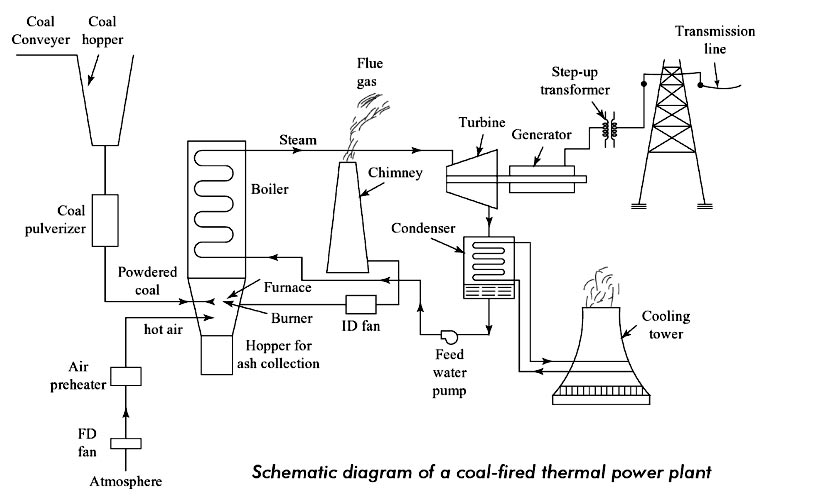
3. Air pollution due to smoke around a thermal power station can be reduced by installing
- Economizer
- Super heater
- Electrostatic precipitator
- Induced draft fan
ID (Induced Draft) fan is always located between dust collector and chimney. ID fan handles the flue gases i.e. hot air. ID fan takes the hot flue gases from the furnace via dust collector (dust separation system or Fume Extraction system) and delivers to the chimney. In the induced draft cooling towers, the fan is located at the top and air enters from the openings located at the bottom. ID produces the pressure lower than the atmospheric pressure in the system or we may say that ID fan will produce the negative pressure inside the furnace to avoid any backfiring through any opening.
Electrostatic precipitator:- An electrostatic precipitator is used before the ID fan to collect the fine dust particles so that they are not thrown into the atmosphere along with the flue gases and pollute the atmosphere. This is a must requirement provided by the environmental protection law, and the power stations have to abide by this requirement of installing dust collectors from the flue gases.
Economizer:- The function of the economizer is to recover a portion of heat from the exhaust gases before the flue gases enter the chimney and discharged to the atmosphere. The economizer is placed in the path of the flue gases in between the boiler exit and entry to the chimney. Feed water coming from the feed pump, when passed through the economizer tubes, absorbs the heat in the exhaust gases. This increases the temperature of water entering the boiler. Due to the high temperature of feed water, fuel consumption reduces, and this increases the overall efficiency of the boiler.
Super heater:- A superheater is a device used to convert saturated steam or wet steam into superheated steam or dry steam. Superheaters are used in steam turbines for electricity generation, steam engines, and in processes such as steam reforming.
4. Directions: It consists of two statements, one labeled as the ‘Statement (I)’ and the other as ‘Statement (II)’. Examine these two statements carefully and select the answer using the codes given below:
Statement (I): The expression for the value of inductance L per conductor of an unsymmetrically spaced 3-phase overhead transmission line contains an imaginary term.
Statement (II):The presence of the imaginary term is due to the mutual inductance between the phase conductors and can be eliminated by symmetrically transposing the three line-conductors along the length of the line.
- Statement (I) is true but statement (II) is false
- Statement (I) is false but statement (II) is true
- Statement (I) and Statement (II) are individually true and statement (I) is the correct explanation of statement (II)
- Statement (I) and Statement (II) are individually true but statement (II) is not the correct explanation of statement (I)
The inductance of three-phase overhead lines with unsymmetrical spacing:
When three-phase line conductors are not equidistant from each other, the conductor spacing is said to be unsymmetrical. Under such conditions, the flux linkages and inductance of each phase are not the same. A different inductance in each phase results in unequal voltage drop in three phases even if the current in the conductors is balanced. Therefore, the voltage at the receiving end will not be the same for all phases. In order that voltage drops are equal in all conductors, we generally interchange the positions of the conductor at regular intervals along the line, so that each conductor occupies the original position of every other conductor over an equal distance. Such an exchange of position is known as transposition, as shown in Figure. In practice, the conductors are so transposed that each of the three possible arrangements of conductors exists for one-third of the total length of the line.
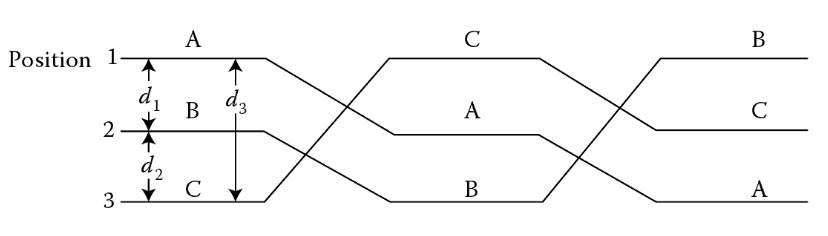
The effect of transposition is that each conductor has the same average inductance, which is given as
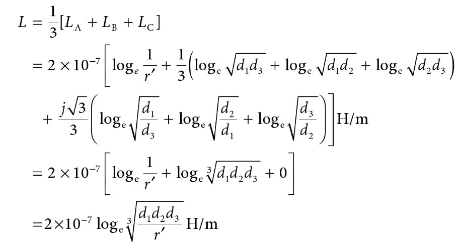
Thus we see that when the conductors of a 3-phase transmission line are not equidistant from each other, i.e., unsymmetrically spaced, the flux linkages and inductances of various phases are different which cause unequal voltage drops in the three phases and transfer of power between phases (represented by imaginary terms of the expression for inductances) due to mutual inductances even if the currents in the conductors are balanced.
5. In distance protection, the relay measures _________.
- Positive sequence impedance of the line from relay up to the fault point
- Self-impedance of the line from relay up to the fault point
- Negative sequence impedance of the line from relay up to the fault point
- Zero sequence impedance of the line from relay up to the fault point
Distance relay: A relay that measures the Positive sequence impedance or a component of the impedance from relay up to the fault point location is known as a distance relay. It is used for the protection of a transmission line. As the impedance of a line is proportional to the length of the line, a relay that measures the impedance or its component is called a distance relay.
Distance protection is a widely used protective scheme for the protection of high and extra-high voltage (EHV) transmission and sub-transmission lines. This scheme employs a number of distance relays that measure the impedance or some components of the line impedance at the relay location. The measured quantity is proportional to the line-length between the location of the relay and the point where the fault has occurred. As the measured quantity is proportional to the distance along the line, the measuring relay is called a distance relay. Overcurrent relays have been found unsuitable for the protection of transmission lines because of their inherent drawbacks of variable reach and variable operating time due to changes in source impedance and fault type. Distance relays have been developed to overcome the problems associated with the use of overcurrent relays for the protection of transmission lines.
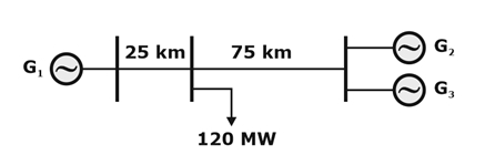
6. A load center of 120 MW derives power from two power stations connected by 220 kV transmission lines of 25 km and 75 km as shown in the figure below. The three generators G1, G2 and G3 are of 100 MW capacity each and have identical fuel cost characteristics. The minimum loss generation schedule for supplying the 120 MW load is?
- P1 = 90 MW, P2 = 15 MW, P3 = 15 MW
- P1 = 80 MW, P2 = 20 MW, P3 = 20 MW
- P1 = 60 MW, P2 = 30 MW, P3 = 30 MW
- P1 = 40 MW, P2 = 40 MW, P3 = 40 MW
Power delivers to load centre = 120 MW
P1 comes from a 25 km transmission line and P2, P3 is from a 75 km line.
- The load is connected through a 25 km & 75 km long transmission line by G1 (100 kW) and G2, G3 (100 MW each) respectively.
- For minimum loss, higher power should come from a shorter distance transmission line connected to the generator. Generally, we supply load from the nearest generator. So a maximum of load should be supplied from G1. But G3 & G2 should be operated at the same minimum generation.
- Therefore, from option P1 = 90 MW, P2 = 15 MW & P3 = 15 MW.
7. A 3 phase induction machine draws 1000 kVA at a power factor of 0.866 lag. A synchronous condenser is connected in parallel to draw an additional power of 750 kVA at a leading pf of 0.707. The power factor of the total load supplied by the mains is
- 0.99 leading
- 0.99 Lagging
- 0.90 Leading
- 0.95 Lagging
Given data for Induction Motor
Apparent Power S1 = 1000 kVA,
Power factor P.F1 = 0.866 lag
Active Power (P1 ) = s cos ϕ = 1000 × 0.866 = 866 kW
Reactive Power (Q1) = (Active Power × Sinφ) ⁄ Cosφ
cosφ = 0.866
Sin2φ = 1 − cos2φ
Sin2φ = 1 − (0.866)2
Sinφ = 0.5
Reactive Power =(866 × 0.5) ⁄ 0.866 = 500 KVAR
Given data for Synchronous condenser
S2 = 750 kVA,
PF2 = 0.707 lead
Active Power (P2 ) = s cos ϕ = = 750 × 0.707 = 530.25 kW
Reactive Power (Q1) = (Active Power × Sinφ) ⁄ Cosφ
cosφ = 0.707
Sin2φ = 1 − cos2φ
Sin2φ = 1 − (0.707)2
Sinφ = 0.707
Reactive Power =(530.25 × 0.707) ⁄ 0.707= -530.25 KVAR (leading Power factor)
Total active power of the system P = P1 + P2
P = 1396.25 kW
Total reactive power Q= Q1 + Q2
Q= 500 – 530.25 = -30.25 KVAR
or
Q = Ptan ϕ
-30.25 = 1396.25 tan ϕ
cos ϕ = 0.99 lead (as reactive power is negative, hence leading power factor)
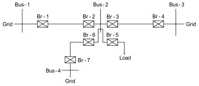
8. The distribution system indicated below is to be protected with overcurrent protection. Identify the locations where essentially directional overcurrent relays will be required considering proper fault discrimination.
- Br-1, Br-4, Br-8 and Br-7
- Br-2, Br-3, Br-5 and Br-6
- Br-2, Br-3 and Br-6
- Br-1, Br-4, Br-7, Br-5
Directional Relay
Wherever power flows in both directions, for example, in the present-day grid system having sources normally at both ends of the transmission line, directional relays are needed. The directional relay is connected in series with the Overcurrent relay so that the trip command is only given if there is a fault and also flow of power due to the fault in the forward direction, i.e. away from the bus. The directional relay is supplied with the current as well as the voltage.
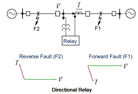
The directional feature can be achieved by comparing the direction of current flow in the line with reference to the bus voltage. In other words, the directional relay measures the phase angle between voltage and current vectors. This is why the directional relay is a two-quantity relay and a phase comparator relay, i.e., voltage and current both are fed to this relay. Directional overcurrent relay employs the principle of actuation of the relay when the fault current flows into the relay in a particular direction. If the power flow is in the opposite direction, the relay will not operate.
Therefore, the test set for the directional relay has current and voltage outputs with a facility to adjust and measure: –
- The magnitude of the voltage and current i.e Power
- The phase angle between the current and voltage
The relay should operate only for the direction in which it has been set to operate and over a certain phase angle zone or range which is measured (within 0 to 360°). If the phase angle is out of this zone then the relay should not operate. Directional relays can respond to positive sequence, negative sequence, or zero sequence inputs. This should be a consideration when applying directional relays at locations where zero sequence voltage is minimal.
Directional overcurrent relays are normally used on incoming line circuit breakers on buses that have two or more sources. They are connected to trip an incoming line breaker for fault current flow back into the source so that a fault on one source is not fed by the other sources.
Coming Back to the Question
BUS-1, BUS-4, and BUS-7 are connected at the grid, therefore there is no need for a directional relay.
BUS-5 is connected at load, therefore directional relay is not necessary here.
BUS-2, BUS-3, BUS-6 are connected with two sources. Therefore, the directional relays are essential in these locations.
9. Surge impedance of Phase, 400 kV transmission line is 200 Ω. The surge impedance loading of the transmission line is
- 1600 MW
- 400 MW
- 800 MW
- 1000 MW
Surge Impedance loading is given by
[katex]SIL = \dfrac{{{V^2}}}{{{Z_C}}}\;MW[/katex]
Where
Surge impedance (ZC) = 200 Ω
Voltage (V) = 400 kV
[katex]SIL = \dfrac{{{{\left( {400 \times {{10}^3}} \right)}^2}}}{{200}} = 800\;MW[/katex]
10. A three-phase metal-sheathed belted cable has a capacitance of 1.2 μF/km between one conductor and the other two conductors bunched together with the earth sheath and 2.4 μF/km between the three bunched conductors and the sheath. The charging current per phase when the cable is connected to 11 kV, 50 Hz supply is _______ (in A)
- 1.54
- 3.43
- 2.79
- 1.58
The capacitance of cable between one conductor and any two cores bunched together with the earth sheath = 2CC + CS
Charging current of cable= VPω C0
Where,
VP = Per phase voltage in volts
ω = 2πf = Angular frequency
f = Supply frequency in Hz
C0 = Equivalent capacitance per phase
CC = Core to core capacitance
Cs = Core to earth or core to sheath capacitance
Given
2CC + CS = 1.2 μf
3CS = 2.4 μf
CS = 0.8 μf
2CC + 0.8 = 1.2
2CC = 0.4 μf
CC = 0.2 μf
C0 = 3CC + CS = 3 × 0.2 + 0.8
= 1.4 μf
[katex]Charging current = {V_p}ω {C_0} = \frac{{11}}{{\sqrt 3 }} \times 2\;π \times 50 \times 1.4 \times {10^{ – 6}} \times {10^3}[/katex]
= 2.791 A/phase.
