Ques 41. For certain geometry and operating voltage of the uncompensated transmission line, the ratio of power transfer capability to the surge impedance loading with increase in length
Increases
Remains unchanged
Decreases
Uncertain
Answer.2. Remain Unchanged
Explanation:
SInce surge impedance and hence SIL is independent of the length of the line. The value of surge impedance will be the same at all the points on the line and hence the voltage.
Ques 42. A 60 Hz, 320 km lossless line has Bending end voltage 1.0 p.u, The receiving end voltage with no load is
1.1 p.u.
1.087 p.u.
1.116 p.u.
1.24 p.u
Answer.2. 1.087 p.u
Explanation:
⇒For Loss-less line at no-load:
Vs = Vr.coshγl……………………….(1)
where γl = jωl√LC
and ω = 2Πf
⇒so, coshγl = cos(jωl√L C) = cos(wl√L C)
=cos(2 Π f l√L C)…………..(2)
⇒In the above question frequency is given = 60 Hz Length of transmission i.e l = 320 km
The time take for the surge to travel distance T =(x/v) s Where x is the distancev is the velocity of the surge which is equal to 3 x 10⁸ m/s
Distance given 600km which is equal to 6 x 10⁵ m therefore, (320 x 103 / 3 x 10⁸) = 0.001 s
Putting all the value in equation number 2 we get
coshγl = cos(2Π x 60 x 320 x 1000 / 3*108) = 0.92
⇒Putting the above value in equation number 1 we get
= Vr = Vs/coshγl
= 1 / 0.92 = 1.087 pu
Ques 43. If a line is 100 % series compensated it may result in series resonance at power frequency of
50 or 60 Hz
100 Hz
25 Hz
150 Hz
Answer.1. 50 or 60 Hz
Explanation:
A full 100 % compensation is should never be used because it would make the line flows extremely sensitive to change in angle between the voltage at the line terminal, and the circuit would series resonant at fundamental frequency i.e 50 or 60 Hz.
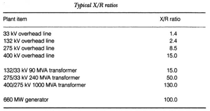
Ques 44. The X/R ratio of 220 kV line as compared to 400 kV line is
Greater
Smaller
Equal
None of the above
Answer.2. Smaller
Explanation:
X/R Ratio
Every electrical circuit contains resistance (R) and inductive reactance (X) and they are electrically in series. Their combined effect is called Impedance.
X depends on the equivalent distance between phases (which increases at higher voltages) and the GMR of the conductor. so you can have (X/R) ratio as high as 10 -15 for a 400 kV line.
Ques 45. A lossless transmission line having surge impedance loading (SIL) of 2280 MW. A series capacitive compensation of 30% is emplaced. Then SIL of the compensated transmission line will be
2725 MW
3125 MW
1800 MW
3200 MW
Answer.1. 2725 MW
Explanation:
Ques 46. A lossless radial transmission line with surge impedance loading
Takes negative VAr at sending end and zero VAr at receiving end
Takes positive VAr at sending end and zero VAr at receiving end
Has flat voltage profile and unity power factor at all points along it
Has sending end voltage higher than receiving end voltage and unity power factor at
Answer.3. Has flat voltage profile and unity power factor at all points along it
Explanation:
For flat voltage profile system, all the voltage drop in the line are neglected therefore supply voltage (Vs) is equal to the Receiving end voltage (Vr) i.e Vs = Vr hence the magnitude of the voltage throughout the line is same.
The characteristic impedance of a lossless transmission line is purely real, with no reactive component. Energy supplied by a source at one end of such a line is transmitted through the line without being dissipated in the line itself.
Therefore the power factor is unity throughout its length.
Ques 47. Bundled conductors are mainly employed to
Decreases system stability
Reduce Sag
Increase the short-circuit current
Reduce Corona effect
Answer.4. Reduce Corona effect
Explanation:
Advantage of Bundled Conductors
By using bundled conductor the self GMD of the conductor is increased
Corona Loss ∝ (V – Vo)2
Where V = R.M.S phase voltage
Vo = Disruptive critical Voltage
Vo is approximately directly proportional to the size of the conductor, therefore, larger the size of the conductor larger the disruptive critical voltage and smaller will be the factor of (V – Vo)2 and hence smaller will be the corona loss.
Ques 48. For a 500 Hz frequency excitation, a 50 km long power line will be modelled as
Short line
Medium line
Long LIne
Data insufficient
Answer.3. Long Line
Explanation:
For one full wave variation, the length of the line for 50 Hz supply will be given as
f λ = v
Where
f =Frequency
λ = length of the line
v = Velocity of the wave i.e 3 x 10⁸ m/s
For 500 Hz
λ = v/f
= 3 x 10⁸ / 500
= 600 Km
Hence the transmission line above 250 Km is treated as Long transmission line.
Ques 49. A single-phase transmission line has 2 parallel conductors 4m apart radius of each conductor being 2 cm. Calculate the capacitance of the line per Km given that Eo = 8.854 x 10⁻¹² F/m
6.12 x 10⁻³F/m
6.48 x 10⁻³F/m
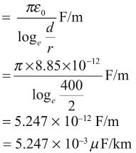
5.247 x 10⁻³F/m
7.248 x 10⁻³F/m
Answer.3. 5.247 x 10⁻³F/m
Explanation:
Conductor Radius = 2 cm
Spacing of conductor = 4 m = 400 cm
Capacitance of the line
Ques 50. What is the time of operation of a relay of rating 5 amp 2.2 sec, IDMT and having a relay of the setting of 125% Tms = 0.6 It is connected to a supply circuit through a CT, 400 ratio. The fault current is 4000 amp.
10.0 sec
1.92 sec
4.5 sec
2.4 sec
Answer.2. 1.92 sec
Explanation:
The pickup value of the relay is 5 amp but the relay setting is 125 %
Operating current of the relay is = 5 x 1.25 = 6.25 Amp
Pulse setting Multiplier PSM is given as
PSM = Fault current / Relay current setting x CT Ratio = 4000 /6.25 x 80 = 8 Amp
After calculating the value of PSM we have to find out the total time of operation of the relay with the help of Time / PSM curve and for the standard 2.2 sec curve the operating time for PSM = 8 is 3.2 sec
Now in the above question, the value of TSM is given which is 0. 6 sec
Then the actual operating time of the relay isPSM x TSM = 3.2 x 0.6= 1.92 sec
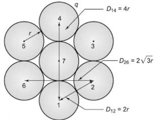
Ques 51. A conductor is composed of seven (7) identical copper each having radius r as shown in the figure. Find the self GMD of the conductor given D14 = 4r D12 = 2r D26 = 2√3r
2.177 r
2.645 r
2.141 r
1.21 r
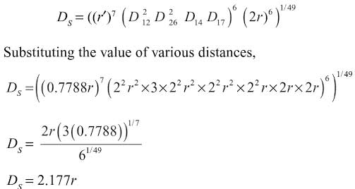
Answer 1. 2.177 r
Explanation:
The self GMD of the seven strand conductor is 49th root of the 49 distance. Thus