The fundamental working principle of an alternator is the same as the DC generator i.e as DC generator an alternator or synchronous generator work on the principle of Faraday’s law of electromagnetic induction.
Faraday’s law of electromagnetic induction states that when a current-carrying conductor is placed in the magnetic field an electromagnetic force (emf) is induced in it.
There are lots of similarities between an alternator and DC generator but there is one difference between them.
Similarity:- Both DC generator and alternator consist of the Armature winding and Field winding.
Difference:- In case of DC generator the armature winding is placed on the rotor and field winding is placed on the stator i.e armature creates the required rotating magnetic field.
But in case of the alternator, the configuration is just reversed that is armature winding is placed on the stator part and field winding is placed on the rotor and it is connected to the DC supply.
Maximum induced EMF in an Alternator
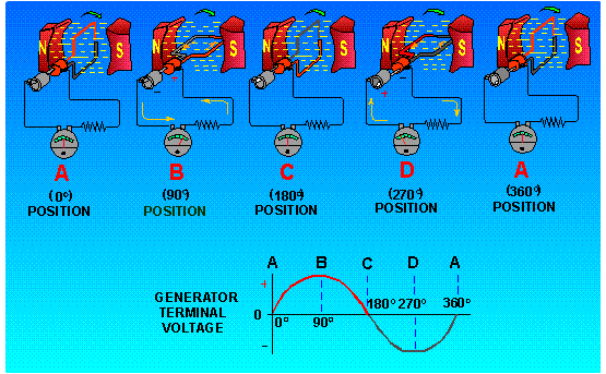
From the above figure consider Position A when the sinθ = 0o in that position the coil is just parallel to the magnetic field therefore very less or no magnetic field line will pass through the conductor hence the flux and current will be zero.
We know that E =Blvsinθ and θ = 0
sin0 = 0
E = 0 (where E is generated voltage)
Now consider Position B when the sinθ = 90oin that particular position the coil is perpendicular to the magnetic field of a line, therefore, the maximum magnetic field line will pass through the conductor so the flux and current generated will be maximum. E =Blvsinθ and θ = 90 sin90 = 1 E = Blv where
E is the generated voltage B is the magnetic flux density l is the length of a conductor in the magnetic field v is the velocity of the conductor
Advantages of Stationary Armature
High Level Of insulation: The alternator is usually designed for high-level voltage operation, therefore, it required good insulation to withstand that high voltage as the stationary winding is free from centrifugal forces hence insulation of winding becomes easier.
Reduce Armature reaction: Due to the stationary armature more cross-sectional area is available hence maximum MMF will be passed from the armature slots, therefore, it reduced armature leakage flux.
No Need of Brushes: The output terminals are fixed on the stator hence output terminal can be taken directly from the fixed output to the load circuit.
Only 2 slip rings are required: If the armature of a three-phase alternator is not stationary (revolving type) then it would require 3 slip rings and for a six-phase alternator, we would be required six slip rings. By making it stationary only two low voltage slip rings are required to excite the field winding by DC current.
Improved heat dissipation and ventilation: Due to low lamination and larger cross-sectional area on stator core the armature winding can be cooled more efficiently as well as effectively.