
Resistors in series | Series Circuit
Circuits
A complete electrical circuit exists when electrons flow along a path between two points. In a complete circuit, resistance must be low enough to allow the available voltage to push electrons between the two points. Most automotive circuits contain four basic parts.
1. Power sources, such as a battery or alternator, that provide the energy needed to cause electron flow.
2. Conductors, such as copper wires, that provide a path for current flow.
3. Loads are devices that use electricity to perform work, such as light bulbs, electric motors, or resistors.
4. Controllers, such as switches or relays, that control or direct the flow of electrons.
There are also three basic types of circuits used in automotive electrical systems: series circuits, parallel circuits, and series-parallel circuits. Each circuit type has its own characteristics regarding amperage, voltage, and resistance.
Resistors in Series
If a number of different circuit components are connected ‘end-to-end’, so that there is only one continuous path for the current to flow along, then these components are said to be connected in series. Therefore in a series circuit, all the resistors are placed one after the other so that the electrical current must flow through each resistor as it flows around the circuit.

Current in a series circuit
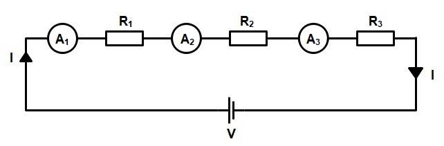
Since there is only one current path, the same amount of current is present throughout the circuit. The current that flows through one resistor also flows through other resistors in the circuit. We can say that ‘the current is common to each component’. Wherever we place an ammeter (a current-measuring instrument) in the circuit, it will give exactly the same reading because it’s measuring exactly the same current — each of the ammeters in the series circuit shown in Figure will register exactly the same value. When a series circuit is opened, there is no path for current flow. Thus, the circuit does not operate.
Voltage drops in a series circuit
The voltages in the series circuit depend on the resistance of the components in the circuit. As that amount of current leaves the battery. it flows through the conductor to the first resistor. At the resistor, some electrical energy or voltage is consumed as the current flows through it. The decreased amount of voltage is then applied to the next resistor as the current flows to it. By the time the current is flowing in the conductor leading back to the battery, all voltage has been dropped. All of the source voltage available to the circuit is dropped by the resistors in the circuit.
If we placed four voltmeters (instruments for measuring voltage) across each resistance, as shown in Figure, we would find that the sum of the voltage readings across each resistance would equal the supply voltage (i.e. the potential difference across the circuit). The voltage drops are the product of the current through the individual resistance and that resistance (i.e. V= IR).
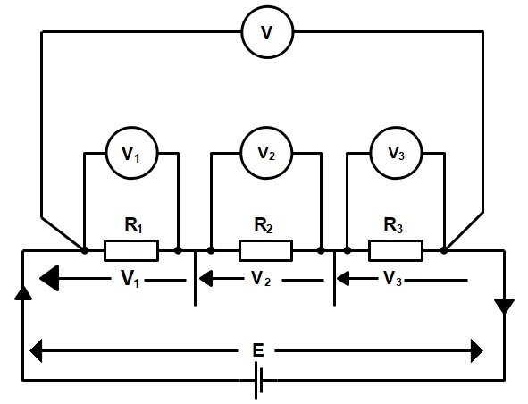
From Kirchhoff’s current law relation, the sum of the voltage drops around any closed path is equal to the supply voltage. This may be expressed as follows:
E = V1 + V2 + V3
From Ohm’s Law, we know that E or V
E or V = IR
Substituting E and V we have
IRT = IR1 + IR2 + IR3
Since the current is common to each resistance, we can divide the whole equation by I
IRT/I = IR1/I + IR2/I + IR3/I
Solving the above equation we get
RT = R1 + R2 + R3
Where RT is the total resistance of the circuit
So for a series circuit, the total resistance is simply the sum of the individual resistance
RT = R1 + R2 + R3
Summary of Series Circuits
There are several important characteristics of series circuits:
- Two devices or elements are connected in series when they have one common node where no other devices have currents flowing through them. In other words, the same current flows through each device, and the current can only flow forward. It basically has a one-way ticket to ride with no alternative routes.
- The total resistance of a series circuit is equal to the sum of the individual resistances.
- The voltage applied to a series circuit is equal to the sum of the individual voltage drops.
- The voltage drop across a resistor in a series circuit is directly proportional to the size of the resistor.
- If the circuit is broken at any point, no current will flow.
Potential hazard of series circuits
Many students believe that if there is a gap in a series circuit (e.g. when a load or a resistance is removed), the voltage across that gap is zero. But this is not true at all. In fact, the voltage across the gap will be equal to the circuit’s supply voltage.
At mains level (i.e. 230 V) or higher supply voltages, an open circuit occurring in a series circuit could result in a potentially hazardous situation. As no current flows, no voltage drops (i.e. the product of current and resistance) can occur across the healthy resistors — leaving the full circuit voltage to appear across the break in the circuit.
Let’s understand this theory by practical example.
Suppose that four resistance are connected in series having the supply voltage of 200 V. Assume that R2 fails (Open) and creates an open circuit.
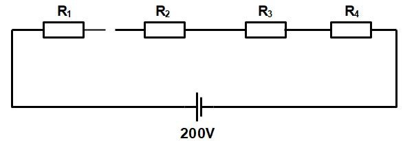
Now in the case of the open circuit, the resistance is infinite therefore the total current in series circuit becomes zero because in a series circuit the total resistance is the sum of individual resistance.
Since no current can now flow, hence voltage drop across the resistance will be zero i.e V1 = 0; V3 = 0 and V4 = 0. Therefore:
E = V1 + V2 + V3 + V4
V2 = E − V1 − V3 − V4
V2 = 200 − 0 − 0 − 0
V2 = 200
From the above discussion it is clear that, In the case of an open circuit in a series circuit, the full supply voltage will appear across the break in the circuit — creating a potentially hazardous situation.
Disadvantages of Series Circuit for Domestic Wiring
The arrangement of lights and various other electrical appliances in the series circuit is not used in domestic wiring because of the following disadvantages:
- In the series circuit, if one electrical appliance stops working due to some defect, then all other appliances also stop working (because the whole circuit is broken). For example, if a number of bulbs are connected in series and just one bulb gets fused (or blows off), then all other bulbs will also stop glowing.
- In the series circuit, all the electrical appliances have only one switch due to which they cannot be turned on or off separately. For example, all the bulbs connected in series have only one switch due to which all the bulbs can be switched on or switched off together and not separately.
- In the series circuit, the appliances do not get the same voltage (220 V) as that of the power supply line because the voltage is shared by all the appliances. The appliances get less voltage and hence do not work properly. For example, all the bulbs connected in series do not get the same voltage of 220 volts of the power supply line. They get less voltage and hence glow less brightly.
- In the series connection of electrical appliances, the overall resistance of the circuit increases too much due to which the current from the power supply is low. Moreover, the same current flows throughout a series circuit due to which all the appliances of different power ratings cannot draw sufficient current for their proper working.
Solved Example of Resistance in series
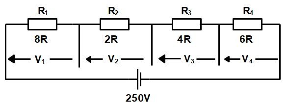
Ques.1. A circuit comprises four components, having resistances of 8Ω, 2Ω, 4Ω, and 6Ω connected in series. If the circuit is connected across a 200-V supply, calculate:
- The total resistance of the circuit
- The current flowing in the circuit
- The voltage drop across each component.
Sol:- The circuit diagram of the above Question is shown in the figure
(1) The total resistance in the circuit
RT = R1 + R2 + R3 + R4
RT = 8 + 2 + 4 + 6
RT = 20Ω
(2) Total current in the circuit
I = V/R = 200/20 = 10A
(3) Voltage across each compnent
V1 = IR1 = 10 × 8 = 80V
V2 = IR2 = 10 × 2 = 20V
V3 = IR3 = 10 × 4 = 40V
V4 = IR4 = 10 × 6 = 60V
For Fundamental Of Electrical Engineering Click Here
For Effect of Temperature On Resistance Click Here
For Concept Of Resistance and Ohm’s Law Click Here
For fundamental-quantities-and-units Click Here