
A resistor connected across the gate and cathode of a thyristor increase its
A resistor connected across the gate and cathode of a thyristor increase its
Right Answer is:
Holding current
SOLUTION
Gate Circuit Parameter
The gate-cathode circuit with different circuit parameters is shown in Fig.
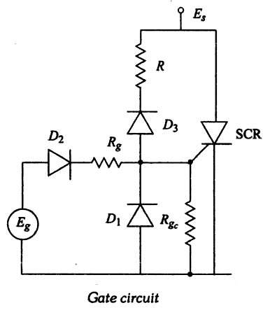
- A series resistance Rg should be placed in series with the gate-source voltage Eg, to limit the magnitude of the gate voltage and gate-current.
- The shunt resistor Rgc is introduced to bypass the thermally generate leakage current across the junction. when the device is in the blocking state, in order to improve the thermal stability of the device. This shunt resistance, in turn, will increase to the required gate current and also the device holding and latching current levels.
- Diode D1 applies a negative voltage between the gate and the cathode when a reverse voltage is applied across the device. This negative gate voltage reduces the reverse blocking current and improves the turn-off mechanism. This diode D1 also serves to limit the reverse voltage applied between the cathode and the gate, if the gate, source voltage Eg is alternating. The negative gate current flows through the device while the SCR is ON because the diode D1 will then be reverse biased. This will increase the dissipation of gate power. A series diode D2 in the circuit will prevent the negative source current. Another diode D3 is connected as shown in the figure to block the positive gate current coming from the supply when the device is homed biased.
- A shunt capacitor Cs may be connected across the gate to the cathode to improve the dv/dt capability. However, pulse firing results in a larger portion of the gate drive being bypassed by the capacitor which will increase the delay time, and consequently the di/dt rating of the device is also lowered. This shunt capacitor also poses one more problem. When the device is turned ON, the gate acts as a voltage source and charges the capacitor. This charge can provide enough gate current after the anode current has stopped thereby increasing turn-off lime of the SCR and commutation may fail.
- If an inductance is connected across the gate to the cathode, the negative gate current is maintained by the inductance even after the anode-current has stopped, and this will facilitate faster turn-off. However, when pulse firing is used for Gating the device, the negative gate current that continues to flow out of the gate can possibly turn off the thyristor.
- Thus, depending upon the specific requirements, gate circuit parameters are chosen. The use of a negative voltage bias between the gate and cathode is generally recommended. This will increase the forward break over voltage and dada withstanding capability. Similarly, the reverse leakage current will also be reduced by the negative gate bias. The only drawback is that a greater gate-source voltage Eg is required to overcome this bias and turn off the SCR.