Hence without knowing the exact value of resistance R, Frequency F, and Inductance L we can’t determine the Impedance Z.
Ques.2. When the frequency of the voltage applied to a series RL circuit is increased, the phase angle
Decrease
Increase
Remain Same
Double
Answer.2. Increase
Explanation:-
The phase angle of an RL circuit is given as
φ = tan−1(ωL/R)
φ = tan−1(2πfL/R)
From the above equation the frequency f ∝ Phase angle φ
By increasing the frequency in the RL circuit the phase angle φ also increases.
Ques.3. When the frequency is decreased, the impedance of a parallel RL circuit
Decrease
Increase
Remain Same
Can’t Say
Answer.1. Decrease
Explanation:-
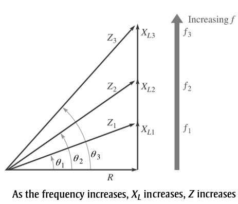
Variation of Impedance and Phase Angle with Frequency
The impedance triangle is important to understand that how the frequency of the applied voltage affects the RL circuit response. The inductive reactance varies directly with frequency. When XL increases, the magnitude of the total impedance also increases; and when XL decreases, the magnitude of the total impedance decreases. Thus, Z is directly dependent on frequency.
The phase angle φ also varies directly with frequency because φ = tan−1(XL/R). As XL increases with frequency, so does φ, and vice versa.
The impedance triangle illustrates the variations in XL, Z, and θ as the frequency changes. Of course, R remains constant. The main point is that because XL varies directly with the frequency, so also do the magnitude of the total impedance and the phase angle.
Ques.4. In an RL circuit, the impedance is determined by both the ______ and the _______ combined.
Ques.5. When the resistor voltage in a series RL circuit becomes less than the inductor voltage, the phase angle :
Decrease
Increase
Remain Same
Can’t Say
Answer.2. Increase
Explanation:-
The resistor and the inductor always share the input voltage. Thus, the resistor too may absorb a part of the input voltage in the circuit. Therefore, the voltage available to the inductor during this interval can only be less than what is available in the source.
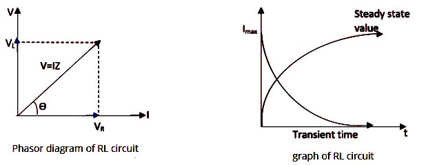
As the resistor voltage tends to increase in the RL circuit the inductor voltages decrease therefore the current increases as shown in the graph.
When the inductor voltage becomes zero then the voltage source output will be across the resistor, and the current will be at its maximum value.
The phase angle is defined as the angle between effective resistance and effective reactance of a circuit.
Cosφ = R/Z.
V = IZ
∴ V of inductor directly proportional to the reactance of inductor.
When Voltage across the inductor is greater than the voltage across Resistor. Then Inductive reactance is greater than the resistance then the circuit becomes inductive in nature and the phase angle increases.
φ = tan−1(XL/R)
In short, if the resistor voltage in a series RL circuit becomes less than the inductor voltage, then the phase angle increases.
Ques.6. A 1.5 kΩ resistor and a coil with a 2.2 kΩ inductive reactance are in series across an 18 V ac source. The power factor is
564
0.564
05.64
56.4
Answer.2. 0.564
Explanation:-
Given Resistance R = 1.5 kΩ
Inductive reactance XL = 2.2 kΩ
The phase angle of an RL circuit is given as
φ = tan−1(XL/R)
φ = tan−1(2.2/1.5)
φ = 55.59°
Power factor = COSφ = C0s(55.59°)
Power factor = 0.564
Ques.7. A 20-H coil is connected across a 110-V 60-Hz power line. If the coil has zero resistance, What will be the value of the current drawn.
12.64 mA
1.46 mA
146 mA
14.6 mA
Answer.4. 14.6 mA
Explanation:-
Inductive reactance XL = 2πfL
XL = 6.28 × 60 × 20
XL = 7536Ω
Current Drawn IL = VL/XL
IL =110/7536 = 14.6 mA
Ques.8. A 140 Ω resistor is in parallel with an inductor having 60 Ω inductive reactance. Both components are across a 12 V ac source. The magnitude of the total impedance is
55.15 Ω
5.51 Ω
0.51 Ω
0.5 Ω
Answer.1. 55.15 Ω
Explanation:-
The Impedance of the Parallel RL circuit is given as