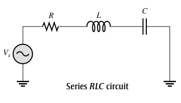
1. In a series, RLC circuit containing resistance, inductance, and capacitance the total reactance is ______ either individual reactance
Greater than
Less than
Equal to
None of the above
Answer.2. Less than
A series RLC circuit contains resistance, inductance, and capacitance. Since inductive reactance and capacitive reactance have opposite effects on the circuit phase angle, the total reactance is less than either individual reactance.
2. In a series RLC circuit when the capacitive reactance is equal to Inductive Reactance then the total reactance is
Zero
Unity
Greater than one
Less than one
Answer.1. Zero
Explanation:-
As we know that, inductive reactance (XL) causes the total current to lag the applied voltage. Capacitive reactance ( (XC) has the opposite effect. It causes the current to lead the voltage. Thus XL and XC tend to offset each other. When they are equal, they cancel, and the total reactance is zero.
3. Resonance is a condition in a series RLC circuit in which the capacitive and inductive reactances are _______ magnitudes.
Greater than
Lesser than
Equal in
None of the above
Answer.3. Equal in
Explanation:-
Resonance is a condition in a series RLC circuit in which the capacitive and inductive reactances are equal in magnitudes.
4. If the value of C in a series RLC circuit is decreased, the resonant frequency _______
Becomes twice
Remain same
Decrease
Increase
Answer.4. Increase
Explanation:-
The resonant frequency in the series RLC circuit is,
From the above equation, the resonant frequency of the series RLC circuit is inversely proportional to the square root of the capacitance.
By the above equation, the value of the capacitance C in a series RLC circuit is decreased, then the resonant frequency in a series RLC circuit is increased.
5. A certain series resonant circuit has a bandwidth of 2 kHz. If the existing coil is replaced with one having a higher value of Q, the bandwidth will
Decrease
Increase
Remain same
None of the above
Answer.1. Decrease
Explanation:-
Q factor or quality factor of RLC circuit is given as
Q = Fr/Bw
Bw = Bandwidth
Fr = Resonance Frequency
From the above equation, it is clear that the quality factor is inversely proportional to the bandwidth hence as Q increases, bandwidth decreases.
Ques.6. A 6.8 kΩ resistor, a 7 mH coil, and a 0.02 µF capacitor are in parallel across a 17 kHz ac source. The coil’s internal resistance, RW, is 30 Ω. The equivalent parallel resistance, Rp(eq), is
1,878 Ω
18,780 Ω
1.8780 Ω
18.780 Ω
Answer.2. 18,780 Ω
It is for internal resistance present in the inductor and capacitor.
Genrally, we solve this problem in tank circuit model
XL=2*3.14*f*L.
Xc=1/(2*3.14*f*C).
After convert all parallel networks into conductance,s uceptance, admitance values
Conductance(G)=(R)/(R^2 + X^2); R=30
In this scenario internal restance present in L&C.
so we are taking suceptance(B)=(X)/(R^2 + X^2); R=30.
Y=y1 + y2 + y3 Here, Y= admitance.
Y=G1+G2 + G3 + J(BL -Bc); G1 value take restor R1=6800 OHM; G2&G3 values take R=30.
After calculation,
Y=G + J(B),
finally R=1/G,
R=18,780 OHMS.
7. The magnitude of the total reactance in the series circuit is
Xtot = |XL + XC|
Xtot = 2|XL + XC|
Xtot = |XL − XC|
Xtot = 2|XL − XC|
Answer.3. Xtot = |XL − XC|
Explanation:-
Inductive reactance (XL) causes the total current to lag the applied voltage. Capacitive reactance ( (XC) has the opposite effect. It causes the current to lead the voltage.
The magnitude of the total reactance in the series circuit is
Xtot = |XL − XC|
The term |XL − XC| means the absolute value of the difference of the two reactances. That is, the sign of the result is considered positive no matter which reactance is greater. For example, 5 − 8 = − 3, but the absolute value is
|5 − 8| = 3
8. In a series RLC circuit when inductive reactance is greater than capacitive reactance (XL > XC) the circuit is predominantly
Capacitive in nature
Inductive in nature
Resistive in nature
Impedance in nature
Answer.2. Inductive in nature
Explanation:-
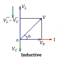
The phase difference (φ) is the angle by which the current drawn from the supply lags or leads the applied voltage in a series RLC circuit. When the inductive reactance is greater than the capacitive reactance the circuit is inductive and the current lags the voltage.
The phasor diagram represents the voltages in the circuit in relation to the current (I) that is the reference phasor. The current (I) is in phase with VR leads VC by 90°. The applied voltage (V) is determined by resolving VL and VC. For inductive load, the applied voltage is (VL — VC).
9. In a series RLC circuit when Capacitive reactance is greater than inductive reactance (XC > XL) the circuit is predominantly
Capacitive in nature
Inductive in nature
Resistive in nature
Impedance in nature
Answer.1. Capacitive in nature
Explanation:-
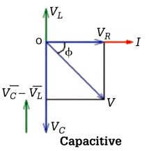
When the capacitive reactance is greater than the inductive reactance the circuit is capacitive and the current leads the voltage. The current (I) is in phase with VR lags VL by 90°. The applied voltage (V) is determined by resolving VL and VC. For capacitive load, the applied voltage is (VC — VL).
10. The impedance of series RLC circuit in rectangular form is given as
Z = R −( jXL − JXC)
Z = R +( jXL + JXC)
Z = R −( jXL + JXC)
Z = R +( jXL − JXC)
Answer.4. Z = R +( jXL − JXC)
Explanation:-
The impedance of the RLC circuit in rectangular form is given as