Ques.21. It is advisable to have _____ power factor.
Low
Large
Zero
No
Answer.2. Large
Explanation:-
The power factor of a circuit is a measure of its effectiveness in utilizing the apparent power. Thus 0.5 pf. of a circuit means that it will utilize only 50% of apparent power whereas OR p.f. would mean 80% utilization of apparent power. For this reason, we wish that the power factor of the circuit should be as large as possible (maximum value is 1).
22. At zero frequency the capacitive reactance is ______
Zero
Maximum
Infinity
Minimum
Answer.3. Infinity
Explanation:-
The capacitive reactance of RLC series circuit is
XC = 1/2πfC
Now f = 0
XC =1/2π0C
XC = 1/0 = ∞
At zero frequency the capacitive reactance is infinity and the capacitor behaves like an open at 0 Hz frequency.
Ques.23. At zero frequency the Inductive reactance is ________
Zero
Maximum
Infinity
Minimum
Answer.1. Zero
Explanation:-
The Inductive reactance of RLC series circuit is
XL = 2πfL
Now f = 0
XL = 2π0L
XL = 0
At zero frequency the Inductive reactance is zero and the capacitor behaves like short at 0 Hz frequency.
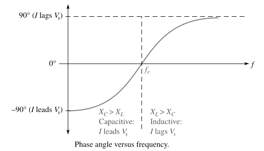
Ques.24. At frequencies below resonance, XC > XL the current _______ the source voltage
Lags
Become twice
Become half
Lead
Answer.4. Lead
Explanation:-
At a frequency below the resonant frequency, current leads the source voltage because the capacitive reactance is greater than the inductive reactance. The phase angle decreases as the frequency approach the resonant value and is 0° at resonance.
Ques.25. At frequencies above resonance, XL > XC and the current _______ the source voltage.
Lags
Become twice
Become half
Lead
Answer.1. Lags
Explanation:-
At frequencies above resonance, the current lags behind the source voltage, because the inductive reactance is greater than capacitive reactance. As the frequency goes higher, the phase angle approaches 90°.
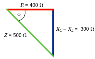
Ques.26. What will be the phase difference of an RLC circuit illustrated by the impedance triangle?
37°
73°
3.7°
7.3°
Answer.1. 37°
Explanation:-
The impedance triangle when XC > XL
tanφ = (XC − XL)/R
tanφ = 300/400
φ = 37°
Ques.27. Find the current in polar form of series RLC circuit when the resistance is 75 kΩ, capacitive reactance is 60 kΩ , inductive reactance is 25 kΩ and the source voltage is 10∠0°.
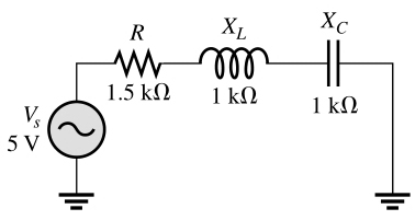
Ques.30. Find I, VR, VL and VC at resonance for the circuit in Figure
I = 3.33 mA, VR = 7.33 V, VL = 3.33V, VC = 3.33 V
I = 7.33 mA, VR = 7.33 V, VL = 3.33V, VC = 3.33 V
I = 333 mA, VR = 7.33 V, VL = 3.33V, VC = 3.33 V
I = 7.33 mA, VR = 7.33 V, VL = 7.33V, VC = 7.33 V
Answer.1. I = 3.33 mA, VR = 7.33 V, VL = 3.33V, VC = 3.33 V
Explanation:-
Given
R = 1.5 kΩ
XC = 1 kΩ
XL = 1 kΩ
At resonance, I is maximum and equal to VS/R
I = VS/R = 5/1.5
I = 3.33 mA
Apply Ohm’s law to obtain the voltage magnitudes.
VR = IR = 3.33 × 2.2 = 7.33 V
VL = IXL = 3.33 × 1 = 3.33 V
VC = IXC = 3.33 × 1 = 3.33 V
All of the source voltage is dropped across the resistor. Also, VL and VC are equal in magnitude but opposite in phase. This causes these voltages to cancel, making the total reactive voltage zero.