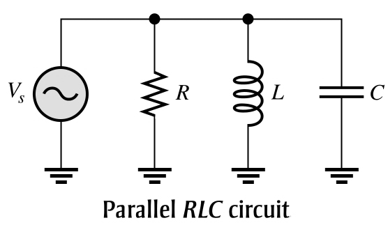
The figure shows a parallel RLC circuit. The total impedance can be calculated using the reciprocal of the sum-of-reciprocals method, just as was done for circuits with resistors in parallel.
Ques.32. For parallel RLC circuits, the phasor expression for Conductance (G) is
G∠90°
G∠180°
G∠−90°
G∠0°
Answer.4. G∠0°
Explanation:-
The conductance, G, is the reciprocal of resistance. The phasor expression for conductance is expressed as
G = 1/R∠0° = G∠0°
Ques.33. For parallel RLC circuits, the phasor expression for Capacitive susceptance (BC) is
jBC
−jBC
2jBL
None of the above
Answer.1. jBC
Explanation:-
Capacitive susceptance (BC) is the reciprocal of capacitive reactance. The phasor expression for capacitive susceptance is
BC = 1/XC∠−90°
BC = ∠90° = jBC
Ques.35. For parallel RLC circuits, the phasor expression for inductive susceptance (BL) is
jBL
−jBL
2jBL
None of the above
Answer.1. jBL
Explanation:-
For parallel RL circuits, the phasor expression for inductive susceptance (BL) is
BL = 1/XL∠90°
BL∠−90° = −jBL
Ques.34. For parallel RLC circuits, the phasor expression for Admittance (Y) is
Y∠θ
Y∠−θ
Y∠2θ
Y∠±θ
Answer.4. Y∠±θ
Explanation:-
Admittance (Y) is the reciprocal of impedance. The phasor expression for admittance is
Y = 1/Z∠ ±θ
Y = ∠ ±θ
Ques.35. In a parallel RLC Resonant circuit, the current in the capacitive branch and the current in the inductive branch are always ____ with each other.
90° out of phase
180° out of phase
180° in phase
90° in phase
Answer.2. 180° out of phase
Explanation:-
Parallel Resonant Circuits
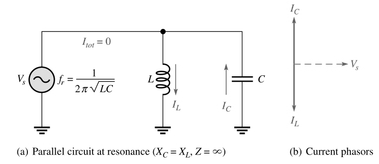
A parallel resonant circuit is formed when the Inductor and capacitor are connected in parallel with the applied voltage. In general, resonance in a parallel tuned circuit can also be defined as the point at which the inductive and capacitive reactances are equal.
If we assume lossless components in the circuit (no resistance), then the current in Parallel resonant circuit the inductor equals the current in the capacitor: Although the currents are equal, they are 180° out of phase, as the phasor diagram in Fig The current in the inductor lags the applied voltage by 90°, and the current in the capacitor leads the applied voltage by 90°, for a total of 180°.
Ques.36. Ideally, the parallel resonance occurs when the
XL > XC
XL < XC
XL > 2XC
XL = XC
Answer.4. XL = XC
Explanation:-
The circuit, with resistance R, inductance L, and capacitance, C in parallel is connected to a single-phase variable frequency (f) supply is called a parallel resonance circuit. The condition for resonance occurs when the susceptance part is zero.
The total admittance of the circuit is
Y = YR + YL + YC
= 1/R + 1/jXL + 1/(−jXC)
= 1/R + j(1/XL − 1/XC)
At resonance condition, the “j” component of admittance is equal to zero.
1/XL − 1/XC = 0
XL = XC
Ideally, parallel resonance occurs when XL = XC. When XL = XC the two branch currents, and are equal in magnitude, and they are always 180° out of phase with each other.
Ques.37. Ideally the parallel Resonance circuit is one that contain only _____ and _______
Inductance, capacitance
Inductance, Resistance
Resistance, capacitance
None of the above
Answer.1. Inductance, capacitance
Explanation:-
The ideal parallel resonant circuit is one that contains only inductance and capacitance. Resistance and its effects are not considered in an ideal parallel resonant circuit, One condition for parallel resonance is the application of that frequency which will cause the inductive reactance to equal the capacitive reactance.
Ques.38. The total current in the parallel resonance circuit is given by the expression
In a parallel RLC circuit, the current in the capacitive branch and the current in the inductive branch are always 180° out of phase with each other (neglecting any coil resistance). Because IC and IL add algebraically, the total current is actually the difference in their magnitudes. Thus, the total current into the parallel branches of L and C is always less than the largest individual branch current.
The current in the resistive branch is always 90° out of phase with both reactive currents.
where ICL is (IC − IL) the total current into the L and C branches.
Ques.39. A parallel resonance circuit is also called as an
Acceptor circuit
Deflector circuit
Rejector circuit
Donor circuit
Answer.3. Rejector circuit
Explanation:-
A parallel resonant circuit, therefore, admits a very minimum current at the resonant frequency. Therefore it can be employed as a “wave-trap” to block as completely as possible any unwanted frequency by tuning the circuit to be resonant at that frequency, Hence the name ‘rejector resonance’ to the parallel resonance.
Ques.40. The current in the perfect parallel resonance circuit is at _______ value.
Maximum
Zero
Minimum
Infinite
Answer.2. Zero
Explanation:-
At a particular frequency (known as the parallel resonant frequency) the reactance of the capacitor, XC, will be equal in magnitude (but of opposite sign) to that of the inductor, XL. When XL = XC the two branch currents, and are equal in magnitude, and, of course, they are always 180° out of phase with each other. Thus, the two currents cancel and the total current is zero in the case of a perfect parallel resonant circuit).
When XL = XC the two branch currents, and are equal in magnitude, and, of course, they are always 180° out of phase with each other. Thus, the two currents cancel and the total current is zero.