
Ques.11. Germanium possesses:-
- Two valence electron
- Three valence electron
- Four valence electron
- Five valence electron
Answer.3. Four valence electron Explanation:- Germanium has 32 electrons(2, 8, 18, 4) and is thus 4 electrons short of having a rare gas structure in the N shell. This means that the germanium atom will combine with 4 neighboring atoms, in order to reach the stable condition with 36 electrons.
Ques.12. Which of the following is not a property of difference amplifier?
- The coupling capacitor is used in it
- It is used to compare two signal
- Difference amplifier yields more than the direct coupled amplifier
- The frequency of difference amplifier remains flat from the zero to high frequency
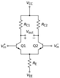
Answer.1. The coupling capacitor is used in it Explanation:- Function of the coupling capacitor In most practical cases, you will not see a single amplifier. Rather than you will see a series of cascaded amplifiers. The term cascaded means connected in series. Coupling capacitors are commonly used to connect one amplifier stage to another. Differential Amplifier The purpose of a differential amplifier is to provide very large amplification to the difference signal and to suppress or eliminate the common-mode signal (average of the two input signals) at the output. This increases the value of the Common Mode Rejection Ratio (CMRR), which is defined as the ratio of differential gain to common-mode gain. Also, the input impedance of the circuit should be very high tending towards several megaohms. In a Differential amplifier, the dc voltage between the two output terminals of the transistors is zero. Thus, the dc quiescent voltage between the two collector terminals will be zero and so, the coupling to the next stage will not affect the quiescent point of that stage. This avoids the coupling capacitor and direct coupling can easily be incorporated without any difficulty. An important advantage of the direct coupling between the stages of an operational amplifier circuit is that it removes the lower cut-off frequency imposed by the coupling capacitors. Therefore, the differential amplifier is capable of amplifying dc as well as ac input signals. A cascaded direct-coupled amplifier can provide high gain down to zero frequency as it has no coupling capacitor.
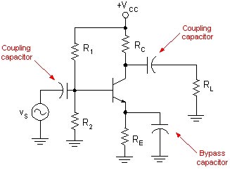
In analog circuits, a coupling capacitor is used to connect two circuits such that only the AC signal from the first circuit can pass through to the next while DC is blocked. This technique helps to isolate the DC bias settings of the two coupled circuits. Capacitive coupling is also known as AC coupling and the capacitor used for the purpose is also known as a DC-blocking capacitor.
Ques.13. For generating large current on DC generators which winding is generally preferred?
- Progressive wave winding
- Lap winding
- Retrogressive wave winding
- Current depends on design
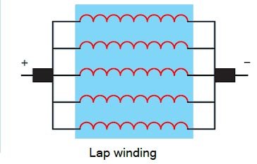
Answer.2. Lap winding Explanation:- Armature Winding Two methods can be used to wound armature coil: Lap winding: Here, the end of one coil is connected to the beginning of the next coil. If connections are made this way the coils look as if they are superimposed on each other and then given a push in one direction as shown in Fig. Lap wound armatures are constructed with relatively few turns of large wire. They are commonly used in machines that are intended to operate on low voltage and high currents, such as starter motors in automobiles, streetcars, and trolleys. Lap wound armatures have their windings connected in parallel with each other.
Ques.14. A.C servomotor is basically a/an ______
- Universal motor
- Single-phase Induction motor
- Two-phase induction motor
- Three-phase induction motor
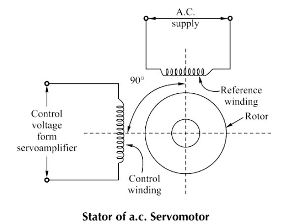
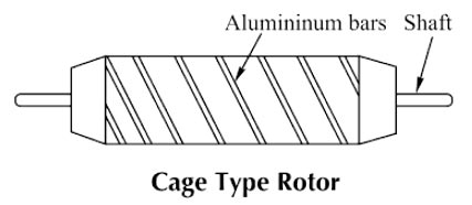
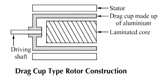
Answer.3. Two-phase induction motor Explanation:- The servomotor is also called a control motor. These motors are used in the feedback control system as output actuators unlike large industrial motors, which are not used for continuous energy conversion. The basic principle of operation of the motor is the same as that of other electromagnetic motors. The rating of the motor varies from a fraction of watt to a few hundred watts. Servomotors are of two types A.C servomotor Most of the servomotors used in the low power servomechanism are A.C. servomotors. The a.c servomotor is a two-phase induction motor. The output power of a.c. servomotor varies from a fraction of watts to a few hundred watts. The operating frequency is 50 Hz to 400 Hz. Construction: The two-phase a.c. the servomotor basically consists of two parts: 1. Stator 2. Rotor. Stator: The stator is the stationary part of the servomotor. The stator carries two windings, uniformly distributed and displaced by 90° in space, from each other. One winding is called as main winding or fixed winding or reference winding. The reference winding is excited by a constant voltage a.c. supply. The other winding is called as control winding. It is excited by the variable control voltage, which is obtained from a servo amplifier. The windings are 90° away from each other and the control voltage is 90° out of phase with respect to the voltage applied to the reference winding. This is necessary to obtain a rotating magnetic field. To reduce the loading on the amplifier, the input impedance i.e., the impedance of the control winding is increased by using a tuning capacitor in parallel with the control winding. Rotor: The rotor is generally of two types. The two types of rotors are: (a) Squirrel cage rotor (b) Drag cup type rotor (a) Squirrel Cage Rotor: The usual squirrel cage rotor has aluminum bars that are shorted at the ends with the help of the end rings. The overall construction looks like a cage. The construction is similar to the squirrel cage rotor used for the three-phase induction motors. This has a small diameter and large length This is because to reduce inertia. Aluminum conductors are used to keeping weight small Its resistance is high to keep torque-speed characteristics as linear as possible. Ai gap is kept very small which reduces the magnetizing current. (b) Drag Cup Type Rotor: To reduce the inertia further, the drag cup type of rotor construction is used. There are tY air gaps in this construction. The drag cap is made up of non-magnetic material like copper, aluminum, or alloy. The slotted rotor laminations are replaced by stationary ring-shaped laminations in this construction. These are wound for as many numbers poles as possible so that the operating speed of the motor is very low. Such construction is used in very low power applications.
Ques.15. The capacitance, in the force-current analogy, is analogous to
- Momentum
- Velocity
- Displacement
- Mass
Answer.4. Mass Explanation:- In the force-current system, the force f(t) is analogous to current i(t), mass M is analogous to capacitance C, viscous friction coefficient B is analogous to conductance G or reciprocal of resistance R, spring constant K is analogous to reciprocal of inductance L and the velocity v is analogous to voltage E. The above analogy is called a force—current analogy and it is called the nodal system.
Ques.16. ________ signal will become zero when the feedback signal and reference signs are equal.
- Input
- Actuating
- Feedback
- Reference
Answer.2. Actuating Explanation:- Actuating signal:- The signal that is the difference between the reference input and the feedback signal. It is the input to the control unit that causes the output to have the desired value. So if the feedback signal and the reference input is equal the actuating signal will become zero.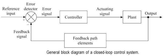
Ques.17. Motor-generator set for DC arc welding has generator of ______
- Series type
- Shunt Type
- Differentially compound type
- Level compound type
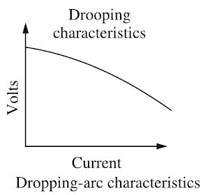
Answer.3. Differentially compound type Explanation:- Arc welding is the widely used method of joining metal parts. Here the source of heat is an electric arc. Arc welding is a group of welding processes wherein the heating is produced with an electric arc or arcs, mostly without the application of pressure and with or without the use of fillet metal, depending upon the base plate thickness. ARC Welding Principle In arc welding, the ARC is generated between the positive pole of D.C. (direct current) called the anode and the negative pole of D.C. called the cathode. When these two poles are brought together, and separated for a small distance (1.5 to 3 mm) such that the current continues to flow through a path of ionized particles, called plasma, an electric arc is formed. Since the resistance of this ionized gas column is high, so more ions will flow from anode to the cathode. Heat is generated as the ions strike the cathode. A.C. or D.C. Machines in ARC Welding Depending upon the application, A.C. or D.C. machines are used in arc welding, but in some cases, either of them can be used. D.C. supply is usually obtained from generators driven by an electric motor or if no electricity is available then the diesel engines can be used. D.C. welding is mostly used for heavy work and at sites where electricity is not available. Arc welding requires a power source that can deliver electrical power at low voltage and high current such that it can establish and sustain an arc plasma column between the welding electrode and the workpiece. The line voltage in the mains supply is too high to be used directly in arc welding. Therefore either a transformer, solid-state inverter/rectifier or a motor-generator set is used to obtain the required open-circuit voltage necessary for arc welding. It is generally in the range of 20-80 V. At the same time the same power source should be capable of delivering high current typically ranging from 50 to 1500 A. This welding power source can have the output of alternating current (AC) or direct current (DC). These power sources have volt-ampere characteristics typically of constant current (CC) or constant potential (CP) type. The output may also have a pulsing mode. A schematic of the basic elements of an arc welding power source is shown in Fig. An arc behaves in a totally different manner from a norms resistance. As the current is increased the potential drop across the arc, instead of increasing as with an ohmic resistance, decreases up to a current of the order of 50-70 A, and then becomes approximately constant. This is because with increasing current arc increases in size, allowing a larger area for curve flow, and also increases in temperature becoming thereby more conducting. The generator used for welding purposes should have high current and low voltage which can be obtained by the differential compound generator. Differentially compounded DC generator has drooping characteristics that mean if load current increases the net flux will decreases(i.e shunt field and series fields in opposition will increases)due to demagnetization effect hence the Induced EMF and terminal voltage decreases.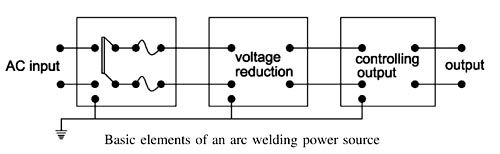
Ques.18. Which of the following motors is preferred when quick speed reversal is the main consideration?
- Squirrel cage induction motor
- Wound rotor induction motor
- Synchronous motor
- DC motor
Answer.4. DC motor Explanation:- There are three different types of DC open-loop motors. All DC motors have an armature, field windings, and housing. How the field windings are set up changes the operating characteristics of the motor. The three ways to set up field windings are In a permanent magnet DC motor, permanent magnets line the inside of the motor housing. The armature is made from a hunk of iron wrapped in multiple turns of copper wire. In series and shunt-wound motors, the field windings are electromagnets, wired to the same power source as the armature. Each of the three methods of DC motor winding has its advantages and disadvantages. In general, permanent magnet and shunt motors are more easily adapted to use as the main drive motors for a robot that is series-wound motors. The problem with series-wound motors is that they are harder to reverse. While permanent magnet and shunt-wound motors can be easily reversed by simply switching the direction of the armature current, a series wound motor must be completely rewired in order to enable the motor to reverse. Permanent magnet DC motors The small DC motors (which have 12V or below 12V) are made up of a permanent magnet i.e. it contains the permanent magnetic field. If you want to change the direction of the shaft you change the polarity only. Because it contains only armature winding only. Temporary magnet DC motors The high voltage DC motors (which has 220V or above 220V) are made up of temporary magnet i.e. field and armature have separate winding. So if you change the polarity of the supply the total circuit will change. Due to that, the motor will rotate in the normal direction. If you want to change the direction of the shaft you need to change either field or armature supply. Take care, that you change either the field or the armature wires. If both are changed at the same time, the direction remains the same. For a brushless DC motor, reversing the supply polarity won’t work and will possibly damage the motor. The electronic commutation needs to be reversible, which has to be part of the motor design. In the case of a single-phase AC motor, the direction can be changed by changing the wiring in the starting circuit In the case of a three-phase induction motor, the direction of rotation can be changed by changing any two of the phases. The direction of rotation of the synchronous motor is determined by its starting direction, as initiated by induction motor action. Thus, to reverse the direction of a 3 phase synchronous motor, it is necessary to first stop the motor and then reverse the phase sequence of the 3 phase connections at the stator. REVERSING THE CURRENT TO FIELD WINDINGS WILL NOT AFFECT THE DIRECTION OF ROTATION. Hence from the above discussion, it is clear that for quick speed reversal the dc motor is more suitable than any other type of motor.
Ques.19. The selectivity of the receiver can be increased by which of the following?
- By using a more tuned circuit
- By decreasing number of the tuned circuit
- By using loudspeaker
- By increasing gain of the receiver
Answer.4. By increasing gain of the receiver Explanation:- Selectivity refers to the ability of a receiver to select a signal of the desired frequency while rejecting all others. Selectivity in a receiver is obtained by using tuned circuits. These are LC circuits tuned to resonate at the desired signal frequency. The Q of these tuned circuits determines the selectivity. Selectivity shows the attenuation that the receiver offers to signals at frequencies near to the one to which it is tuned. A good receiver isolates the desired signal in the RF spectrum and eliminates all other signals. Q is the ratio of inductive reactance to resistance (Q = XL /R), and the bandwidth of the tuned circuit is given by Bw= fr/Q Where fr is the resonant frequency. The bandwidth of a tuned circuit is the measure of selectivity. The gain of the stage is inversely proportional to the bandwidth. In other words, the smaller the ratio of the required bandwidth to the resonant frequency the greater is the possible gain. Narrower the bandwidth the better selectivity. To have a narrower bandwidth and better selectivity the Q of the tuned circuit must be high.
Ques.20. An electronic circuit in which different components such as the diode, resistor, and capacitor etc. are connected separately is called ______
- Chassis
- Printed board
- Integrated circuit
- Discrete circuit
Answer.3. Integrated circuit Explanation:-