A ferrite is a ceramic material made by mixing and firing large proportions of iron(III) oxide (Fe2O3, rust) blended with small proportions of one or more additional metallic elements, such as barium, manganese, nickel, and zinc. They are both electrically non-conductive, meaning that they are insulators, and ferrimagnetic, meaning they can easily be magnetized or attracted to a magnet. Ferrite has a high resistance to demagnetization.
Ques.22. Among the following statement which is false?
Only minority impurities are added in a junction diode
Higher temperature increases the leakage current of the diode
A simple zener is diode work when connected between anode to cathode
Zener is mostly used in voltage regulator
Answer.1. Only minority impurities are added in a junctions diode
Explanation:-
Adding a known amount of impurities (dopants) in a controlled fashion in any intrinsic (pure) semiconductor material can produce extrinsic semiconductor (doped) materials on the basis of the dopant they can be classified as n-type (pentavalent impurities, electrons as majority carriers and holes as minority carriers) or p-type (trivalent impurities, holes as majority carriers and electrons as, minority, carriers semiconductors.
Hence both the majority and minority charge carriers are added to the semiconductor.
Ques.22. Which of the following is the universal gate?
NAND-Gate
OR-Gate
AND-Gate
NOT-Gate
Answer.1. NAND-Gate
Explanation:-
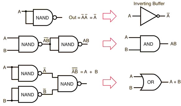
A logic gate is universal if it alone can be used to implement any Boolean function. The NAND and NOR gates are universal. Because NAND and NOR gates are economical and easier to fabricate, they are the basic gates used in all IC Integrated circuits, digital logic families.
It can be seen that the NOT operation requires only one NAND gate.
The AND gate requires 2 NAND gates. The first produces the inverted AND, and the second acts as an inverter to produce the normal output.
The OR gate is realized by a NAND gate, with additional inverters in each input.
Any Boolean function can be implemented by using AND, OR, NOT logic gates. But, we have seen that all these gates can be realized by using NAND gates. Hence, any Boolean function can be realized by using the NAND gates.
Ques.23. What is the unit of electrical energy?
Ampere
Volt
Watt
Kilowatt-hour
Answer.3. Watt
Explanation:-
Electrical Energy
Electric energy is the total amount of electrical work done in an electrical circuit. The electric energy can also be defined as the product of power and time. The S.I Unit of Electrical- Energy is joule or watt-sec.
Ques.24. In resistance heating, the highest working temperature is obtained from heating elements made of
Nickel and copper
Nichrome
Silicon carbide
Silver
Answer.2. Nichrome
Explanation:-
Nichrome (NiCr, nickel-chrome, chrome-nickel, etc.) is any of various alloys of nickel, chromium, and often iron (and possibly other elements).
The Ni-Cr-based heating elements are typical metallic heating elements and are the most popular because they are inexpensive and easy to manufacture. Two types, one is composed of Ni 80% and Cr 20%, whereas the other is composed of Ni 60% and Cr 17% (plus Fe), are most widely used. The oxide film (Cr2O3) formed on the surface of the heating element functions as a protective film.
Heating elements made of Nichrome can be used for continuous operation at a temperature up to 1200oC.
Ques.25. In a resistive load, power dissipation would be proportional to_____
Current
1/Current
(Current)2
1/(Current)2
Answer.3. (current)2
Explanation:-
The rate at which electrical energy is dissipated in the resistor is given as
P = I2 R
Where
I = Instantaneous current in the resistor
Hence power dissipation is directly proportional to the square of the current.
Ques.26. A transistor draws a base current of 100 micro-ampere when the collector current is 10 milliampere. What is the value of the α?
101/100
100/101
1000
10001
Answer.2. 100/101
Explanation:-
Given
Collector current IC = 10 × 10−3 A
Base current IB = 100 × 10−6 A
Emitter Current gain β = IC/IB
β = 10 × 10−3/100 × 10−6
β = 100
Base current gain α = β/β+1
α = 100/101
Ques.27. When the load is above __________ a synchronous motor is found to be more economical?
2 kW
20 kW
50 kW
100 kW
Answer.4. 100 kW
Explanation:-
Explanation:-
A synchronous motor is electrically identical to an alternator or A.C generator. The synchronous motor speed can be controlled by the varying frequency of its source. Due to the non-availability of economical variable frequency sources, speed control of this method was not used in past. These motors are mainly used in constant speed applications.
Synchronous motor drives are close competitors to induction motor drives in many industrial applications and their application is growing. Synchronous motors are generally more expensive than induction motor drives, but the advantage is that the efficiency is higher, which tends to lower the life cycle cost.
The development of semiconductor variable frequency sources, such as inverters and cyclo-converters, has allowed their use in variable-speed applications such as high power and high-speed compressors, blowers, induced and forced draft fans, mainline traction, servo drives, etc. Most synchronous motors are rated between 150 kW and 15 MW and run at speeds ranging from 150 to 1800 rpm.
Synchronous motors are made at speeds from 1800 (two-pole) 150 rpm (48-pole). They operate at a constant speed without slip an important characteristic in some applications. Their efficiency is 1-2 to 5% higher than that of induction motors, the higher value at the lower speeds. They are the obvious choice to drive large low-speed reciprocating compressors requiring speeds below 600 rpm.
Also, the cost per horsepower is generally higher than that of a 3-phase induction motor. Hence synchronous motors are rarely used below 100 kW. because of their much higher initial cost compared to 3-phase induction motors. However, their unique characteristics of constant-speed operation, power-factor control, and high operating efficiency make them highly suitable for heavy industry, particularly for applications requiring low speed and high horsepower.
Ques.28. To convert moving coil galvanometer into an ammeter, which of the following methods is used?
Small resistance in series
Small resistance in parallel
High resistance in series
High resistance in parallel
Answer.1. Small resistance in series
Explanation:-
A galvanometer is converted into an ammeter by connecting a suitable small resistance (called shunt) in parallel with the galvanometer. By doing so the resistance of the ammeter becomes very small and hence, the current to be measured by it does not diminish when it is connected in series with a circuit to measure the current.
An ammeter is a galvanometer with low resistance (shunt) in parallel with it. Since the resistance of the shunt is very small compared to the resistance of the galvanometer, the resistance of the ammeter is always less than that of the galvanometer of which it is formed.
Ques.29. When input signal in the transistor amplifier is applied between the base and emitter and output is taken from emitter and collector, what the configuration is called?
Common emitter
Common base
Common collector
None of these
Answer.1. Common emitter
Explanation:-
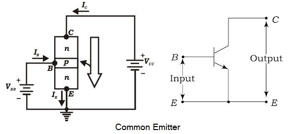
In the common-emitter configuration, the emitter of a transistor is connected to a common terminal between input and output as shown in Fig. The input signal is applied between the emitter and base terminals. The output will be obtained from the collector and emitter terminals. The common emitter configuration of the transistor is the most commonly used one in circuits.
Ques.30. Which of the following can be used to control the speed of the DC motor?
Thermistor
Thyristor
Thyratron
Transistor
Answer.2. Thyristor
Explanation:-
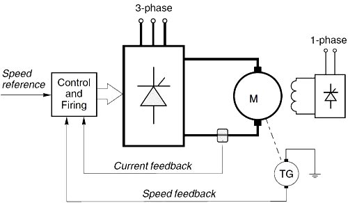
The speed of a dc motor can be varied by varying the armature voltage or the field current, for which a variable dc supply is required. With rapid developments made in the area of thyristors, power converters using them have become very popular in the control of electric drives. The variable dc voltage needed to control the speed of dc motors can be obtained by means of a phase-controlled line commutated converter.
A variable frequency supply is possible by means of inverters employing forced commutation if the ac side of the converter is unable to provide the necessary reactive power for the converter. With the advent of thyristors and developments in integrating circuits for the control of thyristors, there has been a lot of development in the area of inverters making use of forced commutation. These find application in the industry in the area of electric drives. Converters are systems used to transform or control electrical energy using the phase control of thyristors. A thyristor in these circuits periodically provides conducting and non-conducting states alternately, which are used to control the output voltage or output frequency, or both.
Converters, when used to control the speed of a dc motor, are called upon to provide a variable voltage. This is possible by converting the existing ac to dc. The process is called rectification and the converter is a phase-controlled line commutated rectifier. The phase control of thyristors using a control voltage makes it possible to have a variable voltage at the output terminals. Sometimes, the converter is required to allow power flow from a dc load to an ac supply, e.g. during the regenerative braking of a dc motor. The converter performs a function called a synchronous inversion. A converter that can perform both rectification and inversion is called two quadrant converter. The speed of a dc motor can be varied very smoothly and continuously with it.
A dc motor is sometimes required to operate as a variable speed motor in both directions of rotation, with a possibility of regenerative power transfer to the ac supply system. The operation is called a four-quadrant operation.