The methods used for the measurement of medium resistances are not suitable for the measurement of low resistance. This is due to the fact that resistances of leads and contacts, though small, are appreciable in comparison to the low resistance under measurement. For example, the contact resistance of 0.001 Ω causes a negligible error when a medium resistance of value say, 100 Ω is being measured, but the same contact resistance would cause an error of 10% while measuring a low resistance of value 0.01 Ω. Hence the special type of construction and techniques need to be used for the measurement of low resistances to avoid errors due to leads and contacts. The different methods used for measurement of low range resistances are (i) voltmeter—ammeter method, (iii) Kelvin’s double-bridge method, and (iv) potentiometer method.
Ques.52. A time-invariant system is a system whose output
Increases with a delay in input
Decrease with a delay in input
Remains the same with a delay in input
A vanishes with a delay in input
Answer.3. Remain same with a delay in input
Explanation:-
A system is said to be time-invariant when its input/output relationship is constant no matter the time instant where the system is observed. On the contrary, a system whose input/output rule varies with time is a time-varying system.
Ques.53. The primary reason for the low power is due to the installation of the
Induction motor
DC motor
Synchronous motor
Commutator motor
Answer.1. Induction motor
Explanation:-
Power factor is the ratio of real power P to apparent power S or the cosine of the angle between voltage and current in an AC circuit and is denoted by cosΦ. For all types of inductive loads, the angle between voltage V and current I is negative and the cosine of this angle is called the lagging power factor. Similarly, when the angle between V and I is positive it is called the leading power factor (this occurs for capacitive loads).
CAUSES OF LOW POWER FACTOR
The induction motors work at a low lagging power factor at light loads and an improved power factor with increased loads.
The transformers have a lagging power factor because they draw magnetizing current.
Miscellaneous equipment like arc lamps, electric discharge lamps, welding equipment, etc., operates at a low power factor.
The industrial heating Fumaces operate at a low lagging power factor.
The variation of load on the power system also causes a low power factor.
Normally, the power factor of the whole load on a large generating station is in the region of 0.8 to 0.9. However, sometimes it is lower and in such cases In order to improve the power factor, some devices taking leading power should be connected in parallel with the load. This can be achieved by the following equipment
Static capacitors
Synchronous condenser
Phase advancers
Ques.54. How is the condition of the earth electrode measured?
The process of connecting the grounding system to earth is called earthing and consists of immersing a metal electrode or system of electrodes into the earth. The conductor that connects the grounding system to earth is called the grounding electrode conductor. The function of the grounding electrode conductor is to keep the entire grounding system at earth potential (i.e., voltage equalization during lightning and other transients) rather than for conducting ground-fault current.
Earth electrodes are designed by taking into consideration the site conditions and the particular requirements of the installation or facility. Important site conditions include space availability, resistivity, homogeneity of soil, and climatic effects. Generally, the resistance of the volume of earth immediately surrounding the electrode is the predominant component of the total electrode resistance. The earth electrode resistance primarily depends on the physical design of the electrodes and the resistivity of the soil surrounding the electrodes.
The value of earth resistance depends upon the shape, size, and position of the electrode, and the resistivity, moisture content, and degree of ionization of the soil in the vicinity of the electrode. Each type of electrode has its particular niche applications with respect to cost, site conditions, soil structure, and resistivity.
Ques.55. Connection of the various parts of a circuit to the earth has
Medium resistance
High resistance
Very high resistance
Very low resistance
Answer.4. Very low resistance
Explanation:-
The basic measure of the effectiveness of an earth electrode system is called earth electrode resistance. Earth electrode resistance is the resistance, in ohms, between the point of connection and a distant point on the earth called remote earth. Remote earth from the driven electrode is the point where earth electrode resistance does not increase appreciably when this distance is increased. Earth electrode resistance consists of the sum of the resistance of the metal electrode (negligible) plus the contact resistance between the electrode and the soil (negligible) plus the soil resistance itself. Thus, for all practical purposes, earth electrode resistance equals soil resistance.
Earth resistance values should be as low as practicable but are a function of the application. The British Standard makes clear that the total resistance of the complete electrode system (which may well comprise of a number of electrodes) should never exceed 10. Effectively, all the electrodes are interconnected and are thus in parallel with each other. Thus, the maximum resistance to the earth of an individual electrode must never exceed 10 times the number of electrodes.
If, for example, there are eight electrodes, the resistance of any one of them must not exceed 8 x 10 Ω or 80 Ω. It will be appreciated that, in this case, eight resistors, each of 80 Ω and connected in parallel, will have a combined resistance of 10 Ω. Should the resistance to earth of individual electrodes be less than 80 Ω, then the overall resistance to earth will be less than 10 Ω and hence the system will be safer.
Ques.56. If the current of a diode changes from 1 mA to 10 mA, what will be change in voltage across the diode. The ideality factor of diode is 1.2
0.718 V
7.18 V
0.0718 V
0.000718 V
Answer.3. 0.0718 V
Explanation:-
Given
Ideality Factor η = 1.2
I1 = 1 mA
I2 = 10 mA
Vt = thermal voltage = 26 mA
Change in voltage ΔV
ΔV = η Vt ln(I2/I1)
= 1.2 × 26 × 10−3 × ln (10 × 10−3 /1 × 10−3)
= 0.0718 V
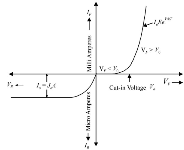
Ques.57. After cut in voltage AC resistance of the diode
Slightly Decrease
Slightly increase
Decrease Exponentially
Increase exponentially
Answer.4. Increase Exponentially
Explanation:-
Cut in voltage:- It is the forward voltage at which the current through the p-n junction starts to increase rapidly. When a diode is forward biased, it conducts current very slowly until we overcome the potential barrier. The value of the potential barrier and hence the cut in voltage for silicon p-n junction is 0.7 V and that for germanium is 0.3 V.
As the applied forward voltage exceeds the cut-in voltage, the current through the p-n junction starts increasing rapidly. Therefore, in order to get useful current through a p-n junction, the applied voltage must be more than the cut-in voltage.
Ques.58. If R1 = 1 ohm, R2 = 3 ohm, R3 = 5 ohm and R4 = 7 ohm connected in series. If the total voltage = 20 V then find current I and V2
I = 1.23, V2 = 3.75
I = 1. 15, V2 = 3.73
I = 1.15, V2 = 3.73
I = 1.16, V2 = 3.72
Answer.1. I = 1. 15, V2 = 3.75
Explanation:-
Since all the resistance are connected in series therefore equivalent resistance will be
R = 1 + 3 + 5 + 7 = 16 ohm
Current in each resistor
I = V/R = 20/16 = 1.25 A
Since in series ciruit the current remain same in all the resistance hence the voltage in resistance R2
V = I.R2 = 1.25 × 3 =3.75 V
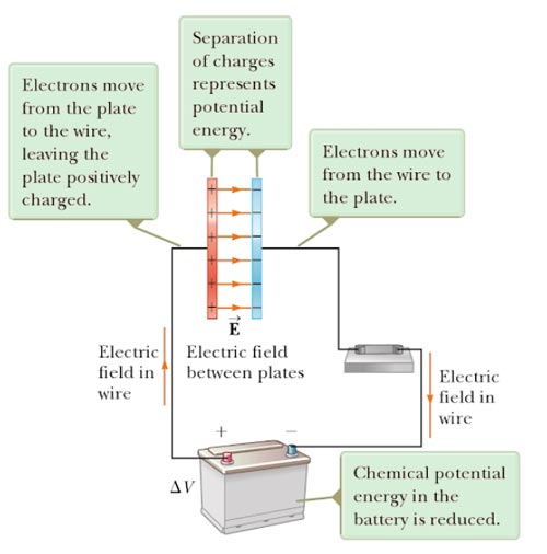
Ques.59. In a charge capacitor, the energy stored in
The field between the plates
The positive charge
The negative charge
None of these
Answer.1. The field between the plates
Explanation:-
In a capacitor, one plate of a capacitor is charged positively, whereas the other plate is charged negatively. If the plates were not separated by an insulating medium, then these charges will have a tendency to cross over and neutralize. These charges are prevented from doing so by inserting an insulating medium. The electrostatic field between these plates constitutes an electric field which can be represented by electric lines of force. The higher the charge on capacitor plates, the stronger will this field be. Because positive and negative charges are separated in the system of two conductors in a capacitor, electric potential energy is stored in the system.
Ques.60. For a D.C shunt motor of 5 kW, running at 1000 RPM the induced torque will be