Ques.21. The short-circuit test in the transformer is used to determine:-
- The iron loss at any load
- The copper loss at any load or at full load
- The hysteresis loss
- The eddy current loss
Answer.2. The copper loss at any load or at full load Explanation:- Short-Circuit Test In the case of short-circuit tests, all the test instruments are connected on the high-voltage side and the low-voltage side is short-circuited. Now, the voltage across the HV side is gradually increased from a very low value. Since the transformer is short-circuited, the rated full-load current will appear at a much lower voltage. Low voltage (5 to 10%) is applied to the primary and slowly increases till full load current is flowing both in primary and secondary. Over and above, the rated full-load current on the high-voltage side is lower than that on the low-voltage side. So, the lower-rated instruments on the primary side can serve the purpose of testing. Now at a low voltage, the exciting current will be much lower. So the effect of iron loss in this test can be neglected. Hence the wattmeter reads the copper loss in the transformer.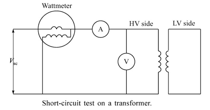
Ques.22. Power diode is
- A three-terminal semiconductor devices
- A two-terminal semiconductor device
- A four-terminal semiconductor device
- A three-terminal analog device
Answer.2. A two-terminal semiconductor device Explanation:- A power diode is a two-terminal semiconductor device with a relatively large single P-N junction. It consists of a two-layer silicon wafer attached to a substantial copper base. The base acts as a heat-sink, support for the enclosure, and also one of the electrical terminals of the diode. The other surface of the wafer is connected to the other electrical terminal. The enclosure seals the silicon wafer from the atmosphere and provides adequate insulation between the two terminals of the diode. The two terminals of a diode are called the anode (A) and the cathode (K). A power diode is more complicated in structure and operating characteristics than a low-power diode Usually, power diodes have high-forward-current carrying capability and high reverse breakdown voltage. The area of the PN junction in a power diode is very high compared to low power signal diodes. Therefore, the structural modification of a low-power signs diode is required to make them suitable for high power applications.
Ques.23. In industries which electrical braking is preferred?
- Regenerative braking
- Plugging
- Dynamic Braking
- All of the above
Answer.4. All of the above Explanation:- Electrical braking is the most important requirement of quick-speed control of a running motor in modern electric drives. The quickness and accuracy of the operations in controlling the speed determine the quality and productivity of the product. Electrical braking is very smooth compared to mechanical braking. The direction of rotation and direction of the developed torque is exactly reversed to each other in electrical braking. The speed-torque characteristics are totally dependent on the method of braking. The three methods of braking are as follows: Regenerative braking:- In regenerative braking, the motor, instead of being disconnected from the supply, remains connected to the supply and returns the braking energy to the supply line. So, the wastage of kinetic energy in the plugging and rheostatic braking methods is prevented in the regenerative braking. However, by this method, the drives cannot be brought to a standstill. It reduces the speed to a minimum permissible value. Dynamic braking:-The supply to the field winding is maintained, but the armature is disconnected from the supply voltage and reconnected to an external resistor. The machine now acts as a generator, converting kinetic energy stored in its moving parts to electrical energy, which is dissipated as heat in the resistor. This method of braking is called dynamic rheostatic braking. Plugging:- Plugging or counter-current braking is a more commonly used method. In this method, the direction of rotation of the machine can be reversed only after reducing the speed to zero. Interchange of any two supplies leads to the staler results in plugging. This reverses the direction of the rotation of the stator MMF, with the rotor still running in the initial condition. The developed electromagnetic torque works in a direction opposite to the direction of rotation of the rotor. This helps to bring the motor to rest quickly. If the supply is not removed at zero speed, the motor runs in the opposite direction. These three types of braking techniques are preferred to stop a DC motor and are used widely in industrial applications.
Ques.24. The steady-state stability of the power system can be increased by
- Using machines of high impedance
- Connecting lines in series
- Connecting lines in parallel
- Reducing the excitation of the machine
Answer.3. Connecting lines in parallel Explanation:- Stability Limit According to the definition, power system stability is the ability of the power system to remain in a balanced condition during the normal operation of the system and to bring back balanced conditions within the minimum possible time after the occurrence of disturbance. Steady-State Stability Steady-state stability refers to system power stability in response to small disturbances and continuous changes in the load. Steady-state stability can be improved by Reduction of transfer reactance A power system that has a lower value of transfer reactance can have a better steady-state stability limit. This can be achieved by: If the power has to be transferred through long-distance transmission lines, the use of parallel lines reduces transfer reactance as well as improves voltage regulations. Similarly, series capacitors are sometimes employed in lines to get the same features.
Ques.25. An AC servomotor operated on the principle of operation of
- AC generator
- Synchronous motor
- Single-phase induction motor
- Two-phase induction motor
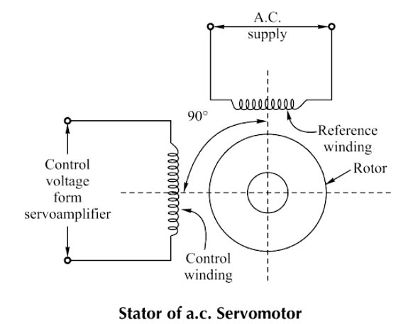
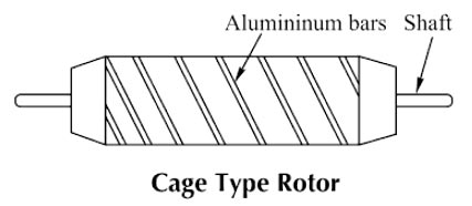
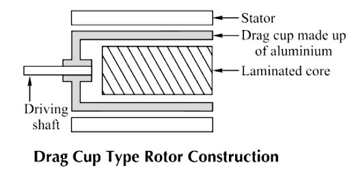
Answer.4. Two-phase induction motor Explanation:- The servomotor is also called a control motor. These motors are used in the feedback control system as output actuators unlike large industrial motors, which are not used for continuous energy conversion. The basic principle of operation of the motor is the same as that of other electromagnetic motors. The rating of the motor varies from a fraction of watt to a few hundred watts. Servomotors are of two types A.C servomotor Most of the servomotors used in the low power servomechanism are A.C. servomotors. The a.c servomotor is a two-phase induction motor. The output power of a.c. servomotor varies from a fraction of watts to a few hundred of watts. The operating frequency is 50 Hz to 400 Hz. Construction: The two-phase a.c. the servomotor is basically consisted of two parts: 1. Stator 2. Rotor. Stator: The stator is the stationary part of the servomotor. The stator carries two windings, uniformly distributed and displaced by 90° in space, from each other. One winding is called as main winding or fixed winding or reference winding. The reference winding is excited by a constant voltage a.c. supply. The other winding is called as control winding. It is excited by the variable control voltage, which is obtained from a servo amplifier. The windings are 90° away from each other and the control voltage is 90° out of phase with respect to the voltage applied to the reference winding. This is necessary to obtain a rotating magnetic field. To reduce the loading on the amplifier, the input impedance i.e., the impedance of the control winding is increased by using a tuning capacitor in parallel with the control winding. Rotor: The rotor is generally of two types. The two types of rotors are: (a) Squirrel cage rotor (b) Drag cup type rotor (a) Squirrel Cage Rotor: The usual squirrel cage rotor has aluminum bars that are shorted at the ends with the help of the end rings. The overall construction looks like a cage. The construction is similar to the squirrel cage rotor used for the three-phase induction motors. This has a small diameter and large length This is because to reduce inertia. Aluminum conductors are used to keeping weight small Its resistance is high to keep torque-speed characteristics as linear as possible. Ai gap is kept very small which reduces the magnetizing current. (b) Drag Cup Type Rotor: To reduce the inertia further, the drag cup type of rotor construction is used. There are tY air gaps in this construction. The drag cap is made up of non-magnetic materials like copper, aluminum, or alloy. The slotted rotor laminations are replaced by stationary ring-shaped laminations in this construction. These are wound for as many numbers poles as possible so that the operating speed of the motor is very low. Such construction is used in very low power applications.
Ques.26. The number of unpaired electrons in the chromium atom is
- 7
- 5
- 6
- 4
Answer.3. 6 Explanation:- The atomic number of chromium is 24 and the number of unpaired electron in the chromium atom is six. 1s22s22p63s23p63d54s1
Ques.27. A transformer has 1000 primary turns. It is connected to 250 V A.C supply. Find the number of secondary turns to get the secondary voltage of 400 volts.
- 625
- 1600
- 400
- 1250
Answer.2. 1600 Explanation:- Given Primary turns N1 = 1000 Primary voltage V1 = 250 V Secondary Turn N2 = ? Secondary voltage V2 = 400 V According to the transformer Ratio N1/N2 = V1/V2 1000/N2 = 250/400 N2 = (1000 × 400)/250 = 1600
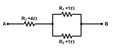
Ques.28. Calculate the total resistance between point A and B
- 4.05Ω
- 8.67Ω
- 0.26Ω
- 0Ω
Answer.1. 4.05Ω Explanation:- The resistance R1 and R2 are in parallel therefore R = R1 || R2 R = (1 × 1)/(1 + 1) R = 0.5Ω Now resistance R and R3 are in series hence Reqv = 4 + 0.5 = 4.05Ω Reqv = 4.05Ω
Ques.29. If 4V is supplied to a 5F capacitor. Find the charge stored in the capacitor.
- 10 C
- 20 C
- 30 C
- 40 C
Answer.2. 20 C Explanation:- Given V = 4 V Capcitance = 5F Charge stored in the capacitor Q = CV = 5 × 4 = 20 V
Ques.30. What happens to the effective inductance when a ferromagnetic core is introduced?
- Increases
- Decreases
- Remain the same
- Becomes Zero
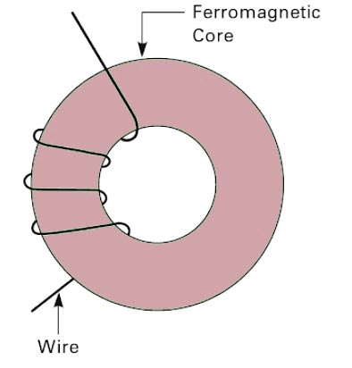
Answer.1. Increases Explanation:- An inductor is an electrical component formed by a coil of wire. Inductors store energy in a magnetic field that is set up when current flows through the coil of wire. The magnetic field returns to zero when the current ceases to flow through the inductor. An inductor’s ability to set up a magnetic field is called inductance and is measured in Henrys (H). Inductance is represented by the letter L. Construction An inductor is usually made from a coil of conductive wire wrapped around a core material. The core performs two functions: (1) it stabilizes the wire and provides support around which to wind the wire One type of core is an air-core which consists of a cylinder of cardboard, wood, or ceramic that may be hollow. Basically, it is a form for winding the wire and does not affect the value of inductance. Another type of core is made of a ferromagnetic material such as iron, nickel, or iron ferrite. This type of core material concentrates the magnetic field and increases the inductance of the inductor. Factors Affecting Inductance Inductance is a function of the number of wire turns, length of the coil, the cross-sectional area of the coil, and permeability of the core material. The inductance of a cylindrical inductor can be calculated by the proportion L = µ.N2.A/L where L is inductance (Henrys) Permeability is a measure of how easily a magnetic field can be generated in a material. The higher a material’s permeability, the easier it is to establish a field. Note that inductance increases by the number of turns of wire squared, so the number of turns has a significant effect on the inductance of the inductor. Ferromagnetic materials have a considerable effect on magnetic fields. Magnetic fields tend to concentrate in high-permeability materials. For example, in the ferromagnetic-core inductor, we indicated that the magnetic flux was confined to the ferromagnetic core.
(2) it increases the inductance, depending on the type of core material.
µ is core permeability (Henrys per meter)
A is a cross-sectional area (square meters)
L is the length of the core (meters)
N is the number of turns of wire.