Ques.11. In the forging operation, fullering is done to
- Draw out of the material
- Bend the material
- Upset the material
- Extrude the material
Answer.1. Draw out of the material Explanation:- Forging is the operation where the metal is heated and then a force is applied to manipulate the metal in such a way that the required final shape is obtained. Forging is generally a hot working operation though cold forging is used sometimes. Fullering is a specialized forth of drawing out. In fullering operation, the material cross-section is decreased and length increased. To do this, the bottom fuller is kept in the anvil hole with the heated stock over the fuller. The top fuller is then kept above the stock and then with the sled hammer, the force is applied on the top fuller. The fullers concentrate the force over a very small area, thus decreasing the cross-section at that point Metal flows outward and away from the center of the fullering die.
Ques.12. Which one of the following is not a fusion welding process?
- Gas Welding
- Arc Welding
- Brazing
- Resistance Welding
Answer.3. Brazing Explanation:- Fusion welding processes are the welding processes that we use without pressure. Even though the fusion welding processes are different from one another, in all the fusion welding processes, the base metal melts and flows into a weld joint. We normally use a filler metal for fusion welding. Then the filler metal also melts and flows into the weld joint. When the molten metal solidifies, it produces a solid fusion weld. The three major types of fusion welding processes are as follows Brazing Brazing is a joining process. In brazing metal or alloy having a melting point below than the parent, metal is made to flow by capillary action into Space between the parts to be joined under the action of heat. Brazing may be defined as the technique of joining two similar or dissimilar materials by the addition of special filler metal. If the alloy used has a melting point lower than 450°C, the technique is known as the soldering Brazing gives~ a much stronger joint than soldering. The filler metal used in brazing is known as a spelter. In brazing, metallic parts are joined by a nonferrous metal or alloy. The melting temperature of a spelter should be above 427°C and brazing is carried out above this temperature. [ninja_tables id=”29216″]
Ques.13. The true centrifugal casting method is used for casting articles
- Symmetrical shape about a vertical axis
- Symmetrical shape about the horizontal axis
- Irregular shape
- Non-ferrous metal only
Answer.2. Symmetrical shape about the horizontal axis Explanation:- Centrifugal casting: It is commonly carried out in a permanent mold that is rotated during the solidification of a casing. Impurities are collected in the center of the casing. True centrifugal casting method is used to produce cast iron and steel pipes. The centrifuge casting method is used for casting articles of symmetrical shape about a horizontal axis. These articles have a fine-grained structure. In true centrifugal casting is the mold is rotated about its own axis without using a central core. If the mold is partially filled, a hole appears along the center of rotation of the casting, the diameter of the hole determined by the amount of metal used. The weight of casting produced to that of metal poured approaches 1:1. 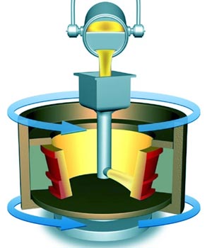
Ques.14. The purpose of jigs and fixtures is to
- Increase machining accuracy
- Facility interchangeability
- Decrease expenditure on quality control
- Decrease machining accuracy
Answer.2. Facility interchangeability Explanation:- Production devices are generally working holders with/without tool guiding/setting arrangement. These are called jigs and fixtures. Jigs are provided with tool guiding elements such as drill bushes. These direct the tool to the correct position on the workpiece. Jigs are rarely clamped on the machine table because it is necessary to move the jig on the table to align the various bushes in the jig with the machine spindle. Fixtures hold the workpiece securely in the correct position with respect to the machine /cutter during operation. There is sometimes a provision in the fixture for setting the tool with respect to the workpiece/fixture, but the tool is not guided as in a jig. Fixtures are often Camped to the machine table. Elements of Jigs and Fixtures Generally, all the jigs and fixtures consist of: Advantages of Jigs and Fixtures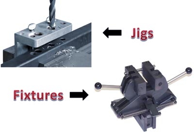
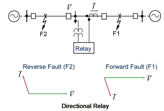
Ques.15. Directional relays are based on the flow of
- Power
- Voltage Wave
- Current
- Field
Answer.1. Power Explanation:- Wherever power flows in both directions, for example, in the present-day grid system having sources normally at both ends of the transmission line, directional relays are needed. The directional relay is connected in series with the Overcurrent relay so that the trip command is only given if there is a fault and also flow of power due to the fault in the forward direction, i.e. away from the bus. The directional relay is supplied with the current as well as the voltage. The directional feature can be achieved by comparing the direction of current flow in the line with reference to the bus voltage. In other words, the directional relay measures the phase angle between voltage and current vectors. This is why the directional relay is a two-quantity relay and a phase comparator relay, i.e., voltage and current both are fed to this relay. Therefore, the test set for the directional relay has current and voltage outputs with a facility to adjust and measure: – The relay should operate only for the direction in which it has been set to operate and over a certain phase angle zone or range which is measured (within 0 to 360°). If the phase angle is out of this zone then the relay should not operate. Directional relays can respond to positive sequence, negative sequence, or zero sequence inputs. This should be a consideration when applying directional relays at locations where zero-sequence voltage is minimal.Directional Relay
Ques.16. In the fuel cell ________ energy is converted into electrical energy.
- Mechanical
- Heat
- Sound
- Chemical
Answer.4. Chemical Explanation:- Chemical energy is a form of potential energy. It is related to the structural arrangement of atoms or molecules, which is a result of the chemical bonds. The chemical energy of a substance can be converted into other forms of energy through chemical reactions. For example, the chemical energy of a fuel is converted to heat energy when it is burned. Similarly, the digestion of food metabolized in an organism involves the conversion of chemical energy into heat energy. Conversely, other forms of energy can be converted into chemical energy. For example, green plants convert solar energy into chemical energy through photosynthesis, and electrical energy is converted into chemical energy through electrochemical reactions. The fuel cell was invented by William R Grove in 1839. It was then called a gaseous voltaic battery. A fuel cell is an electrochemical device that converts chemical energy (of a fuel) directly into electrical energy. Since the chemical energy of the fuel is directly converted to electricity, a fuel cell can operate at much higher efficiencies than internal combustion engines, extracting more electricity from the same amount of fuel. Fuel cells are capable of converting 40% of the available fuel to electricity. Ibis can be raised to 80% with heat recovery. The fuel cell itself has no moving parts, offering a quiet and reliable source of power. Electrochemical energy conversion is galvanic when electrical energy is generated by the cell reaction, while the reverse process of using electrical energy to produce chemical energy is electrolytic. Fuel cells are considered galvanic electrochemical cells which convert the chemical energy of a continuously supplied fuel and oxidant combination directly into electrical energy
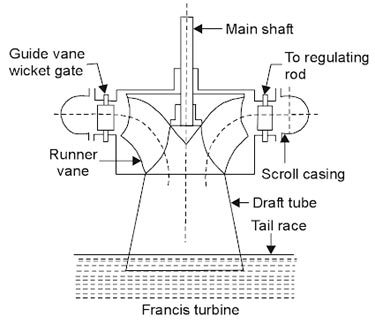
Ques.17. Francis turbine is usually used for
- Medium heads
- Lower heads
- Higher Heads
- Lower medium and higher heads
Answer.1. Medium heads Explanation:- Turbines are classified as given below: The inward flow reaction turbine having radial discharge at the outlet is known as Francis turbine, after the name of J.B. Francis an American engineer who at the beginning designed inward radial flow reaction turbine. The flow of water in the turbine may be radially from outward to inward or from inward to outward. but in both cases, the flow passing through the runner has the velocity component in a plane normal to the axis of the runner. In modern Francis, turbine water enters the runner of the turbine in the radial direction at outlet and leaves in the axial direction at the inlet of the runner. Thus the modern Francis turbine is a mixed now type of turbine in which water enters radially at its outer periphery but leaves axially at its center. Working of Francis Turbine Since the modern Francis turbine is a mixed flow type, the water enters radially at the outer periphery of the runner and levee axially. These turbines operate under medium heads and require a medium quantity of water. The water first passes through guide vanes, which in turn direct the water at the proper angle so that the water enters the runner vanes without shock and glides properly. As the water passes through the runner and proceeds towards an outlet. Some part of the head acting on the turbine is transformed into a kinetic head and the rest remains pressure head. There is a difference of pressure between guide vanes and the runner is called reaction pressure. The reaction pressure is responsible for the motion of the runner. Since the pressure al inlet of the turbine is much more than the pressure at the outlet, the water in the turbine must flow in a closed conduit and the runner should always be full of water. After passing through the runner the seater is discharged to tailrace through a draft tube of suitable shape and size.
Ques.18. The angle between rotating stator flux and rotor poles is called
- Torque angle
- Obtuse angle
- Synchronizing angle
- Power factor angle
Answer.1. Torque angle Explanation:- Effect of load on Synchronous motor When the mechanical load on a D.C. motor or an A.C. motor is increased, the speed decreases This, is turn, decreases the back or counter e.m.f. (Eb) so that the source is able to supply more current to meet the increased load demands. However, this action cannot take place in the synchronous because the rotor must run at the synchronous speed at all loads. Fig. (a) shows the relative position of a stator and rotor pole at no load, poles centers are directly inline with each other. Fig. (b ) represents the relative position of the stator and the rotor poles after a mechanical load has been added to the motor. Now there has been a shift of the rotor pole in a direction opposite to that of the stator field flux and the direction of the rotor. It may be kept in mind that there has been no change in speed as the rotor will continue to rotate at synchronous speed. There is only an angular displacement between the centers of the stator and rotor field poles. The angular displacement shown is called the Torque angle.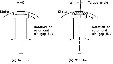
Ques.19. Which of the following motors is used in tape recorders?
- Reluctance motor
- Capacitor motor
- Universal motor
- Hysteresis motor
Answer.4. Hysteresis motor Explanation:- The hysteresis motor can be considered as a self-starting synchronous motor. From the time of starting until it reaches synchronous speed, the motor produces a synchronizing torque and an ideally flat speed/torque characteristic. Due to the absence of slots and teeth on the rotor, the operation of this motor is smooth and quiet as there is no mechanical vibration. The motor behavior is similar to that of a conventional synchronous motor but there is no excitation winding on the rotor or permanent magnets, giving the motor a high efficiency and power factor. These characteristics make it ideal for many industrial applications, such as in electronic and medical equipment, tape and video recorder drives, computer drives, clocks, gyroscope rotors for inertial navigation, robotics, and other special applications where precision and reliability are required.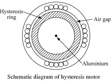
Ques.20. Slip rings for induction motors are made up of
- Cobalt steel
- Aluminum
- Carbon
- Phosphor bronze
Answer 4. Phosphorus Bronze Explanation: