
Basic Electrical | Series and Parallel circuit | Series Parallel circuit
Series Parallel Circuit
Combination electrical circuits are made up of both series and parallel parts some load units are connected in series and some are connected in parallel. They are sometimes called series-parallel circuits. Almost all electrical equipment has combination circuits rather than only series circuits or only parallel circuits. However, it is important to understand series and parallel circuits in order to work with combination circuits.
Characteristics of Series-Parallel Circuit
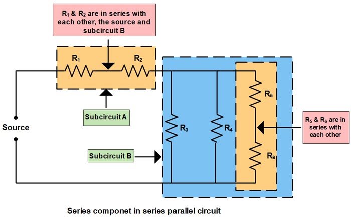
(1) Series components in a series-parallel circuit may be in series with other individual components, or with other combinations of components as shown in the figure.
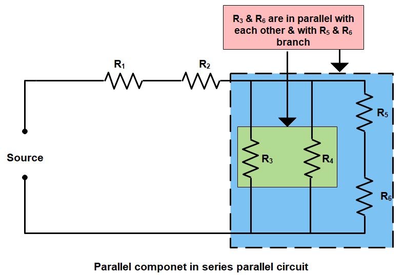
(2) Parallel components in a series-parallel circuit may be in parallel with other individual components, or with other combinations of components, as given in the figure below.
Approach to Identify and Analyze Series and Parallel Circuit
1). One of the best ways to identify series and the parallel circuit is to start analyzing the portion of the circuit farthest from the source and work back toward the source to identify those components that are in series and in parallel.
2) Trace common current paths to identify components in series as shown in the figure. As we already discussed in the post “Series circuit“ that Components or combinations of components with common current are in series with each other.
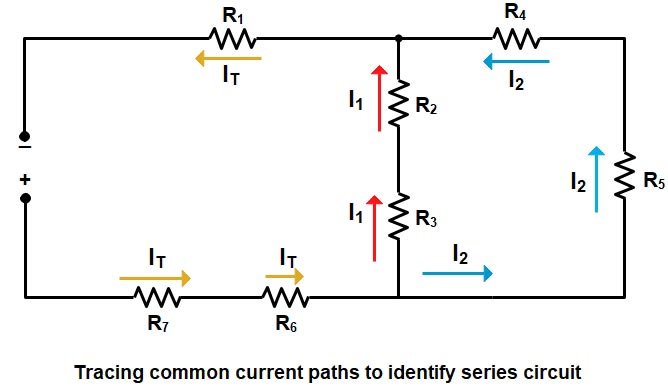
From the above figure, we will now identify the series resistance. Starting “away from the source” and working back
- R4 and R5 have common current (I2) thus they are in series with each other.
- R2 and R3 have common current (I1 ) and are in series with each other.
- R1, R6, and R7 have common current (IT) and they are in series with each other, and with the total parallel combination of the R2 + R5 branch in parallel with the R4 + R5 branch.
3) Now we will identify the parallel resistance by observing common voltages shared component or resistance in a circuit. As we know that in PARALLEL CIRCUIT, the components or combinations of components with the same voltage connection points (at both ends) are in parallel with each other as shown in the figure.
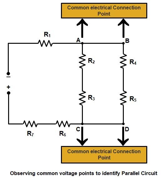
- By looking at the above circuit we can identify that Points A and B are electrically the same point and points C and D are electrically the same points. Therefore, the voltage from point B to point C is the same as the voltage from point A to point D.
- Branch 2 i.e (R4 + R5) is across the same potential as branch 1 i.e (R2 + R3). Therefore, branch 1 and branch 2 are in parallel with each other.
4) Another method to find the Parallel connection of the circuit is by observing current branching and converging points to identify components, or combinations of components that are in parallel with each other, as given in the circuit diagram below
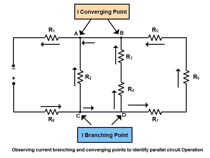
- A point where current splits, or branches, is one end of a parallel combination of components, i.e points C and D.
- The point where those same currents converge (or rejoin) is the other end of that same parallel combination, i.e points A and B.
5). In summary, in the series portions of the circuit, the current is common and the voltages (and resistances) are additive. In the parallel portions of the circuit, voltage is common and the branch currents are additive.
Method For solving Series-Parallel circuit
So far, we have understood very well that what is the difference between series and parallel resistance. Theoretically, we can easily differentiate between them but while solving complex circuit most of the student failed to apply the concept or they find difficult to identify the series and parallel component in the circuit.
Today I will be discussing some easy methods to solve the complex circuit. These methods are very easy to understand and it will clear all your doubts.
Solved Numerical of Series-Parallel Circuit
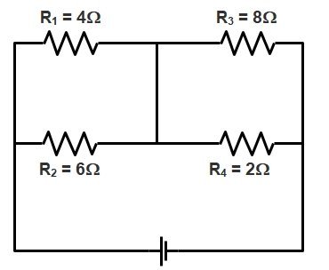
Ques.1. Find the total equivalent resistance of the circuit in the diagram given below?
To identify whether the resistance is connected in series or in parallel consider the following method
- Use one color for each continuous wire
- DO NOT cross any circuit elements
- Any element that shares the same two colors are in parallel
- Any element that shares different colors are in series
Now we will redraw the circuit with different colors as shown in the below figure
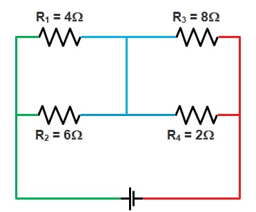
As you can see from the above figure the resistance R1 & R2 share two common colors i.e Green and Blue hence this two resistance are in parallel.
Similarly, the resistance R3 & R4 share two common colors i.e Red and Blue hence this two resistance are in parallel.
Therefore equivalent resistance for R1 and R2 is
R = (4 × 6) ⁄ (4 + 6) = 2.4 Ω
Similarly, the equivalent resistance for R3 and R4 is
R = (8 × 2) ⁄ (8 + 2) = 1.6 Ω
Now the circuit is simplified as shown in the figure
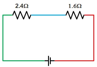
Since the resistance don’t share a common node or color hence they are connected in series
Req = 2.4 + 1.6 = 4Ω
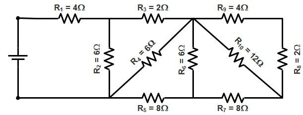
Ques.2. What will be the equivalent resistance (in Ω) for the circuit given below?
Sol:- We will use the “COLOR WIRE METHOD” to solve this problem. Here are some important points we will follow in this method.
- Use one color for each continuous wire
- DO NOT cross any circuit elements
- Any element that shares the same two colors are in parallel
- Any element that shares different colors are in series
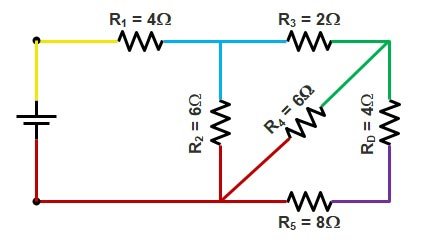
We will now redraw the circuit by using different colors as shown in the figure
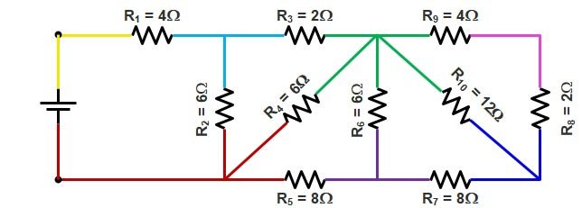
After looking at the circuit many students will think that all the resistance end are connected with a different color wire, therefore, all the resistance are connected in series !!!!! But wait it is not the case. We will calculate the resistance “Away from the source”
Step1.
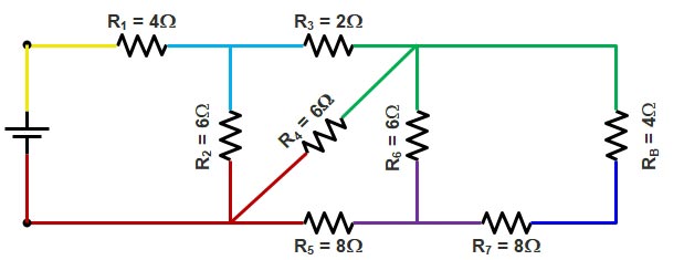
From circuit diagram Resistance R9 and R8 share two different colors, therefore, they are in series with each other. Hence equivalent resistance RA is
RA = 4Ω + 2Ω = 6Ω

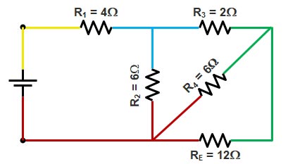
Step 2.
Now the resistance RA and resistance R10 share two common colors i.e Blue and Green, hence they are in parallel with each other.
Now equivalent resistance RB will be
RB = R10 || RA = 12Ω || 6Ω
RB = (12 × 6) ⁄ (12 + 6) = 4Ω
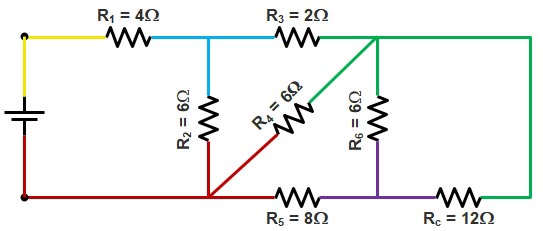
Step 3.
Resistance R7 and RB share different colors hence are in series.
Equivalent resistance RC
RC = 8Ω + 4Ω = 12Ω
Step 4.
Resistance RC and R6 share two common colors i.e Green and Violet hence they are in parallel.
Equivalent resistance RD
RD = RC || R6 = (12 × 6) ⁄ (12 + 6) = 4Ω
Step 5.
Resistance R5 and RD are in series since they share two different colors.
Equivalent Resistance RE
RE = 4Ω + 8Ω = 12Ω
Step 6.
Resistance RE and R4 will be in parallel because they share two same colors i.e Green and Red.
Equivalent Resistance RF
RF = RE || R4 = (12 × 6) ⁄ (12 + 6) = 4Ω
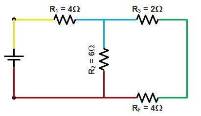
Step.7
Resistance RF and R3 share different colors hence they are in series.
Equivalent Resistance RG
RG = 4Ω + 2Ω = 6Ω
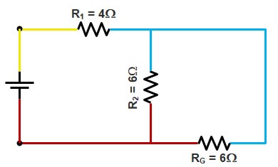
Step.8
Resistance R2 and RG are connected to the same color wire hence they are in parallel.
Equivalent resistance RH
RH = R2 || RG = (6 × 6) ⁄ (6 + 6) = 3Ω
Step.9
Now Resistance R1 and RH are in series because the are connected with two different wire color
Equivalent Resistance REq
REq = 3Ω + 4Ω = 7Ω
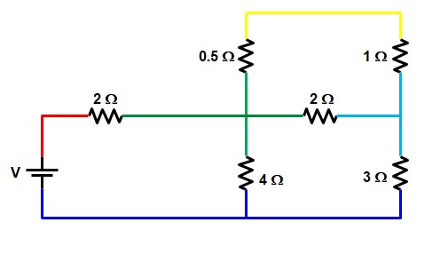
Ques.3. Determine the equivalent resistance (in ohms) for the circuit given below.
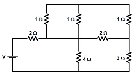
Sol:- To identify whether the resistance is connected in series or in parallel consider the following method
- Use one color for each continuous wire
- DO NOT cross any circuit elements
- Any element that shares the same two colors are in parallel
Now the circuit will look as shown below
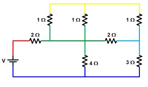
As you can see from the above figure the two resistance of 1 ohm each share two common colors i.e yellow and green hence these two resistances are in parallel.
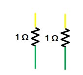
1Ω II 1Ω = (1 × 1) ⁄ (1 + 1) = 0.5 Ω
Again redraw the circuit as shown in figure
Now the yellow wire is connected to only the resistance of 0.5 Ω & 1 Ω hence this two resistance are in series,
R = 0.5 + 1 = 1.5 Ω
Now again redrawing the circuit we get
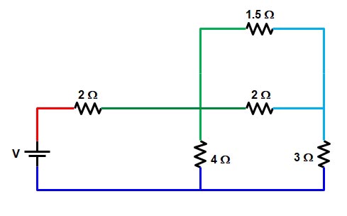
From the above figure, it is clear that the resistance 1.5 Ω and resistance 2 Ω share the same two colors i.e green and sky blue therefore this two resistance are connected in the series.
R = 1.5 || 2 = ( 1.5 × 2) ⁄ (1.5 + 2)
R = 6/7 Ω
Again redrawing the circuit we get
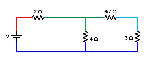
The sky blue wire is connected to the only resistance 6/7 Ω and 3Ω hence they both are connected in series, therefore,
R = 6/7 + 3 = 27 ⁄ 7 Ω
Redraw the given circuit
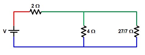
The resistance 4 Ω and the resistance 27/7 Ω is connected to the same wire i.e green and blue hence this two resistance are connected in parallel
R = 4 || 27/7 = ( 4 × 27/7) ⁄ (4 + 27/7) = 1.96 Ω
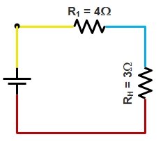
Now the final circuit is shown below
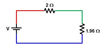
Now the green wire is connected to the only resistance of 2 Ω & 1.96 Ω
R = 2 + 1.96 = 3.96 ≅ 4Ω
For Resistance In Parallel | Parallel circuit Click Here
For Resistance in series | Series Circuit Click Here
For Fundamental Of Electrical Engineering Click Here
For Effect of Temperature On-Resistance Click Here
For Concept Of Resistance and Ohm’s Law Click Here
For fundamental-quantities-and-units Click Here