
Ques 21. In a split-phase motor, the auxiliary winding is made up of
- Thick wire placed at top of the slot
- Thin wire placed at the bottom of the slot
- Thick wire placed at bottom of the slot
- Thin wire placed at top of the slot
Explanation:
Split-Phase Motors
- Split-phase motors receive their name from the manner in which they operate, based on the principle of the rotating magnetic field.
- A rotating magnetic field cannot be produced with only one phase.
- The current is split through two separate windings with a phase displacement, which acts like a 2-phase system.
- A rotating magnetic field can be produced with a 2-phase system. Split-phase motors start as 2-phase motors by producing an out-of-phase condition for the current in the run winding and the start winding.
- The starting winding is wound in the same slots of the stator poles as the running windings.
- This starting winding is displaced 90 electrical degrees out of phase with the running winding and creates a phase displacement that provides enough starting torque to start the motor.
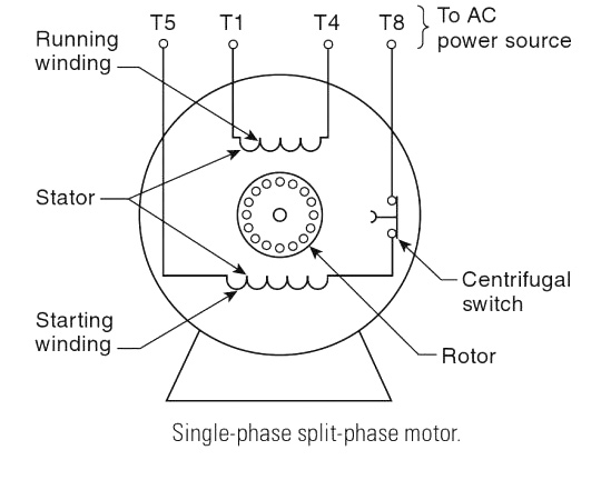
- A startup winding, also known as the auxiliary winding, is used to create the torque needed to start a single-phase induction motor.
- The starting winding is of higher resistance made up of thin wire and occupies a smaller area than the running winding.
- In comparison, the running winding is of lower resistance and has heavier gauge wire and more turns than the starting winding.
- The running winding is wound in the bottom of the stator pole slots, and the starting winding is wound on top of the running winding.
Ques 21. In a two-value capacitor motor, the capacitor used for running purposes is
- Paper spaced oil-filled type
- Air capacitor
- Ceramic type
- None of the above
Explanation:
The capacitor-start capacitor-run motor is also called the two-value capacitor motor. In this motor, the high-starting torque of the capacitor-start motor is combined with the good running performance of the capacitor-run motor.
Motor Capacitors
Start and Run Capacitors:- The two capacitors encountered with single-phase AC induction motors, the start and run capacitors, are different from one another and are not interchangeable.
Start capacitors are usually large microfarad (100 µF to 1,000 µF) AC electrolytic and are designed to be in the energized circuit for only a short period of time.
Run Capacitors:–
- Motor run capacitors are non-polarized and are much larger physically for a much smaller µF capacitance.
- Run capacitors do not depend on a chemical reaction to achieve their capacitance, so they can be across the AC power supply line indefinitely.
- Run capacitors are usually small microfarad (5 µF to 50 µF) made up of expensive oil or pyranol-insulated foil paper capacitor and are designed to be in the energized circuit for extended periods of time.
- Run capacitors are designed for continuous duty while the motor is powered, which is why electrolytic capacitors are avoided.
Ques 22. In a shaded pole motor, the direction of rotation of the motor is
- From shaded pole to the main pole
- From the main pole to the shaded pole
- Either 1 or 2
- None of the above
Explanation:
SHADED-POLE MOTORS
The shaded-pole motor has the lowest starting torque of all the single-phase motors. It is relatively inexpensive and is used to turn very small fan blades connected directly to the shaft of the motor. The basic construction of this motor is very simple since no start winding is present. The imbalance in the magnetic field needed to produce rotation is obtained by shading a portion of the run winding with heavy copper wire or band.

When the motor is energized, the strength of the magnetic field is different in the area of the main poles than in the area of the shaded poles, allowing the rotor to turn.

The direction of rotation of a shaded-pole motor is determined by the orientation of the main poles and the shaded poles. The rotor will turn in the direction indicated by the arrows in Figure. Shaded-pole motors are used for very small applications and are rated in watts instead of horse-power. They normally range in size from 6 watts to roughly 35 watts. This is the equivalent of 1/125 horse-power to 1/20 horsepower. The direction of rotation is from the unshaded portion of the pole to the shaded portion of the pole.
Ques 23. The direction of rotation of the universal motor can be reversed by reversing the flow of current through
- Field winding
- Armature winding
- Either 1 or 2
- None of the above
Explanation:
The universal motor is often referred to as an AC series motor. This motor is very similar to a DC series motor in its construction in that it contains a wound armature and brushes. The universal motor, however, has the addition of a compensating winding.
Reversing Direction of Rotation of Universal Motor
The direction of rotation of a universal motor can be changed by either:
(i) Reversing the field connection with respect to those of armature
(ii) By using two field windings wound on the core in opposite directions so that the one connected in series with armature gives clockwise rotation, while the other in series with the armature gives counterclockwise rotation.
The second method, i.e., the two field method is used in applications such as motor-operated rheostats and servo systems. This method has somewhat simpler connections than the first method.
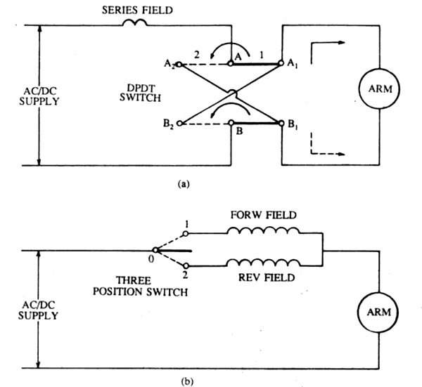
The direction of rotation of the universal motor can be changed in the same manner as changing the direction of rotation of a DC series motor. Reversing the direction of rotation of a universal motor happens by reversing the direction of current in either the series field or the armature but not both.
Ques 24. Which motor is normally free from mechanical and magnetic vibrations?
- Capacitance motor
- Hysteresis Motor
- Reluctance Motor
- Split phase motor
Explanation:
The hysteresis motor can be considered as a self-starting synchronous motor. From the time of starting until it reaches synchronous speed, the motor produces a synchronizing torque and an ideally flat speed/torque characteristic. Due to the absence of slots and teeth on the rotor, the operation of this motor is smooth and quiet. Since the rotor has no salient poles or windings of any sort, the hysteresis motor is extremely quiet in operation and free from mechanical and magnetic vibrations.

The motor behavior is similar to that of a conventional synchronous motor but there is no excitation winding on the rotor or permanent magnets, giving the motor a high efficiency and power factor. These characteristics make it ideal for many industrial applications, such as in electronic and medical equipment, tape and video recorder drives, computer drives, clocks, gyroscope rotors for inertial navigation, robotics, and other special applications where precision and reliability are required.
Since the rotor has no salient poles or windings of any sort, the motor is extremely quiet in operation and free from mechanical and magnetic vibrations. Hence, a hysteresis synchronous motor is ideally suited for driving
Ques 25. In a hysteresis motor, the rotor must have
- High resistivity
- High retentivity
- High susceptibility
- None of the above
Explanation:
The rotor of the Hysteresis Motor is the smooth cylindrical type that is made up of hard magnetic material like chrome steel or alnico for high retentivity (it is the capacity of an object to retain magnetism after the action of the magnetizing force has ceased. This requires selecting a material with a high hysteresis loop area. The rotor does not carry any winding. The stator construction is either split phase type or shaded pole type.
The motor starts rotating due to eddy current and hysteresis torque developed on the rotor At synchronous speed, there is no induced emf in the rotor, as the stator synchronously rotating field and the rotor is stationary with respect to each other.
In the absence of induced eddy current, the torque due to eddy current is zero. At synchronous speed, the rotor torque is only due to the hysteresis effect.
When the rotor rotates at synchronous speed, the stator revolving field flux induces Poles on the rotor. Due to the hysteresis effect, the rotor polarities linger an instant after the stators
Ques 26. The rotor of a hysteresis motor is made of
- Copper
- Cast iron
- Aluminium
- Chrome steel
Explanation:
The rotor of the Hysteresis Motor is the smooth cylindrical type that is made up of hard magnetic material like chrome steel or alnico for high retentivity (it is the capacity of an object to retain magnetism after the action of the magnetizing force has ceased. This requires selecting a material with a high hysteresis loop area. The rotor does not carry any winding. The stator construction is either split phase type or shaded pole type.
The motor starts rotating due to eddy current and hysteresis torque developed on the rotor At synchronous speed, there is no induced emf in the rotor, as the stator synchronously rotating field and the rotor is stationary with respect to each other.
In the absence of induced eddy current, the torque due to eddy current is zero. At synchronous speed, the rotor torque is only due to the hysteresis effect.
When the rotor rotates at synchronous speed, the stator revolving field flux induces Poles on the rotor. Due to the hysteresis effect, the rotor polarities linger an instant after the stators
Ques 27. In a split-phase motor, the main winding is of
- Thick wire placed at the top of the slots
- Thick wire placed at the bottom of the slots
- Thin wire placed at the top of the slots
- Thin wire placed at the bottom of the slots
Explanation:
Split-Phase Motors
- Split-phase motors receive their name from the manner in which they operate, based on the principle of the rotating magnetic field.
- A rotating magnetic field cannot be produced with only one phase.
- The current is split through two separate windings with a phase displacement, which acts like a 2-phase system.
- A rotating magnetic field can be produced with a 2-phase system. Split-phase motors start as 2-phase motors by producing an out-of-phase condition for the current in the run winding and the start winding.
- The starting winding is wound in the same slots of the stator poles as the running windings.
- This starting winding is displaced 90 electrical degrees out of phase with the running winding and creates a phase displacement that provides enough starting torque to start the motor.
- A startup winding, also known as the auxiliary winding, is used to create the torque needed to start a single-phase induction motor.
- The starting winding is of higher resistance made up of thin wire and occupies a smaller area than the running winding.
- In comparison, the running winding is made up of thick wire of low resistance and high inductance, running winding has heavier gauge wire and more turns than the starting winding.
- The running winding is wound in the bottom of the stator pole slots, and the starting winding is wound on top of the running winding.
Ques 28. In repulsion motor, maximum torque is developed when
- Brush axis coincides with the field axis
- Brush axis is at 90° electrical to the field axis
- Brush axis is at 45° electrical to the field axis
- None of the above
Explanation:
Repulsion motor
- The direction of rotation is determined by the position of the brushes with respect to the magnetic field of the stator. Hence we can change the direction of the motor by changing the brush positions.
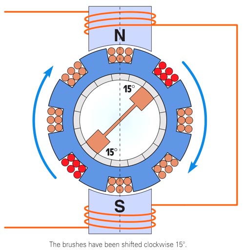
- If the brushes are shifted clockwise from the main magnetic axis, the motor will rotate in a clockwise direction.
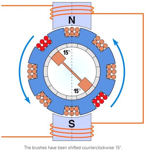
- If the brushes are shifted counterclockwise from the main magnetic axis, the motor will rotate in a counter-clockwise direction.
Operating principle of repulsion Motor
This motor has a wound rotor that functions similarly to a squirrel-cage rotor. It also has a commutator/brush assembly. The brushes are shorted together to produce an effect similar to the shorted conductors of a squirrel-cage rotor. The position of the brush axis determines the amount of torque developed and the direction of rotation of the repulsion motor.
Brush Position of repulsion Motor
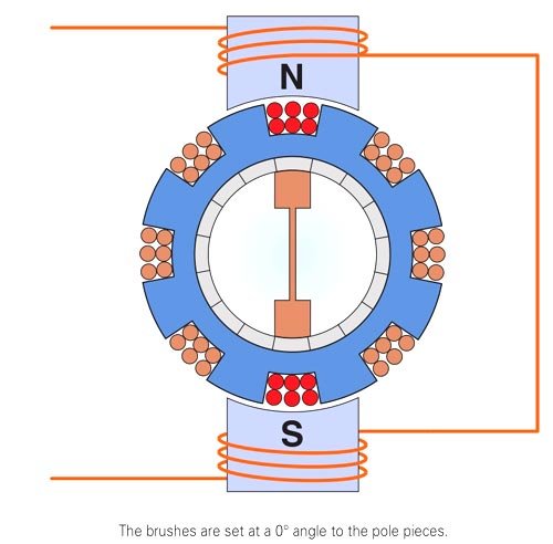
The position of the brushes is very important. Maximum torque is developed when the brushes are placed 15° on either side of the pole pieces. When the brushes are position are placed at 90°, a circuit is completed between the coils located at a right angle to the poles. In this position, there is no induced voltage in the armature windings and no torque is produced by the motor.
In Figure, the brushes have been moved to a position so that they are in line with the pole pieces. In this position, a large amount of current flows through the coils directly under the pole pieces. This current produces a magnetic field of the same polarity as the pole piece. Because the magnetic field produced in the armature is at a 0° angle to the magnetic field of the pole piece, no twisting or turning force is developed and the armature does not turn.
When the brushes have been shifted in a clockwise direction so that they are located 15° from the pole piece. The induced voltage in the armature winding produces a magnetic field of the same polarity as the pole piece. The magnetic field of the armature is repelled by the magnetic field of the pole piece, and the armature turns in the clockwise direction.
When the brushes have been shifted counterclockwise to a position 15° from the center of the pole piece. The magnetic field developed in the armature again repels the magnetic field of the pole piece, and the armature turns in the counterclockwise direction.
The direction of armature rotation is determined by the setting of the brushes. The direction of rotation for any type of repulsion motor is changed by setting the brushes 15° on either side of the pole pieces. Repulsion-type motors have the highest starting torque of any single-phase motor.
The torque in repulsion motor is given as,
${T_e} = \frac{K}{2}{\left( {{I_s}{N_s}} \right)^2}\sin 2\alpha$
From the torque equation of repulsion motor, maximum torque is achieved when stator and rotor magnetic axis are displaced from each other by 45°.
Note:-
- When the brushes are at 90° electrical to the field axis or pole pieces then no torque is developed because the equal induced voltages in two halves of the armature winding will oppose each other hence there will be no induced current in the armature winding, therefore, no flux will be developed by the armature winding.
- Torque is developed when the brush position is 0° – 45° on either side of the pole.
Ques 29. If the centrifugal switch does not open at 70 to 80 percent of the synchronous speed of the motor, it can
- Damage to the starting winding
- Overloading of running winding
- Damage to the centrifugal switch
- None of the above
Explanation:
- A centrifugal switch is connected in series with the starting winding and placed inside the motor.
- An auxiliary winding is for getting the motor started by providing initial torque and some phase differences are not made for running purposes.
- Therefore it is advisable to disconnect the starting winding from the supply when the motor reaches 70 – 80% of its rated full-load speed otherwise it can damage the starting winding.
- Most of the troubles in single-phase induction motors are traceable to the centrifugal switch connected in series with the starting winding.
- In normal use, the contact gap of the switch changes due to arcing and pitting.
- If the starting switch fails to open when needed, the starting winding will almost always overheat and burn out. If the next attempt is made to start the motor. it will result in a growling sound and no rotation. This can cause the failure of the main winding unless the fuse blows out.
- The centrifugal switch is necessary because most motors use an electrolytic capacitor that can only carry AC current for a short period.
