Ques.21. A reluctance motor (SSC-2018 Set-4)
- Self-Starting Motor
- Constant Speed Motor
- Need no-dc excitation
- All of the above
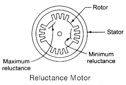
Answer.4. All of the above Explanation:- It is a single-phase synchronous motor which does not require d.c. excitation to the rotor. Its operation is based upon the following principle: Whenever a piece of ferromagnetic material is located in a magnetic field, a force is exerted on the material, tending to align the material so that reluctance of the magnetic path that passes through the material is minimized. Working Principle The stator consists of a single winding called main winding. But single winding cannot produce a rotating magnetic field. So for production of rotating magnetic field, the must be at least two windings separated by the certain phase angle. Hence staler consists of an additional winding called auxiliary winding which consists of the capacitor in series with it. Thus there exists a phase difference between the currents carried by the two winding and corresponding fluxes. Such two fluxes react to produce the rotating magnetic field. The technique is called split phase technique of production of rotating magnetic field. The speed of this field is the synchronous speed which is decided by the number of poles for which stator winding is wound. The rotor carries the short-circuited copper or aluminum bars and acts as the squirrel cage rotor of an induction motor. If an iron piece is placed in a magnetic field, it aligns itself in a minimum reluctance position and gets locked magnetically. Similarly, in the reluctance motor, the rotor tries to align itself with the axis of the rotating magnetic field in a minimum reluctance position. But due to rotor inertia, it is not possible when the rotor is at standstill. So the rotor starts rotating near synchronous speed as a squirrel cage induction motor. When the rotor speed is about synchronous, the stator magnetic field pulls the rotor into synchronism i.e. minimum reluctance position and keeps it magnetically locked. Then the rotor continues to rotate with a speed equal to synchronous speed. Such a torque exerted on the rotor is called the reluctance torque. Thus finally the reluctance motor runs as a synchronous motor. The resistance of the rotor must be very small and the combined inertia of Me rotor and the load should be small to run the motor as a synchronous motor. Advantages The reluctance motor has the following advantages Limitations The reluctance motor has the following limitationReluctance Motor
Ques.22. The speed control of a universal motor used for sewing machines is done by (SSC-2018 Set-4)
- Friction
- Varying the resistance
- Tapping the field
- Centrifugal Mechanism
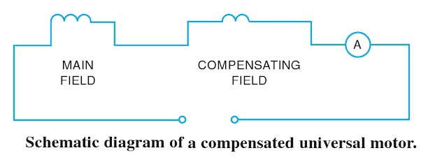
Answer.2. Varying the resistance Explanation:- The universal motor is one which operates both on A.C and D.C supply. Its principle of operation is the same as that of a de series motor, i.e., force is created on the armature conductors due to the interaction between the main field flux and the flux created by the current-carrying armature conductors. Since the universal motor is series wound, it has performance characteristics similar to a In a universal motor, the third set of coils called compensating windings is connected in series with the rotor and stator. These windings perform two functions: They correct the neutral plane position that is distorted by armature reaction, and they compensate for undesirable reactive voltages attributed to the inductance of the armature. The speed of a universal motor is determined by the following factors: Universal motors are speed-regulated by inserting resistance in series with the motor. The resistance may be tapped resistors, rheostats, or tapped nichrome wit coils wound over a single field pole. The resistance is connected before the motor, therefore the current to the motor is reduced, which in turns reduces the speed of the motor according to the setting of that variable resistance. An application example is a sewing machine. Its speed is varied by a foot pedal, Chicle contains a variable resistor. Another example is a variable-speed hand drill. As the trigger is pulled, resistance in series with the motor is changed to vary the RPM. By tapping a field coil at various points, as shown in Figure, different inductive reactance values are developed. When the switch is set at the low-speed position, the entire winding is used and the maximum inductive reactance forms and causes minimum current to flow. At the high-speed position setting, the entire coil is bypassed and the inductive reactance is reduced, causing a higher current to flow. An application example of this principle is a blender. A different field pole connection is made for each speed position setting.
Resistance Method for Speed control of Universal Motor
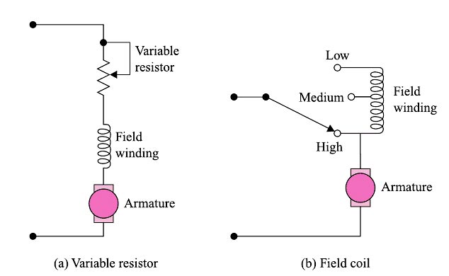
Field Tapping Method of speed control of universal motor
Ques.23. The power factor of a single-phase induction motor is usually (SSC-2018 Set-4)
- Lagging
- Always Leading
- Unity
- Unity to 0.8 leading
Answer.1. Lagging Explanation:- The induction motor, of course, takes electrical power and converts most of it to mechanical shaft power; and, when it does, it absorbs the electrical power. Here the current always lags the voltage or is said to have a lagging power factor.
Ques.24. Hysteresis motors are suitable for (SSC-2018 Set-4)
- Fans
- Blowers
- Sound equipment
- Mixer Grinder
Answer.3. Sound Equipment Explanation:- The hysteresis motor can be considered as a self-starting synchronous motor. From the time of starting until it reaches synchronous speed, the motor produces a synchronizing torque and an ideally flat speed/torque characteristic. Due to the absence of slots and teeth on the rotor, the operation of this motor is smooth and quiet as there is no mechanical vibration. The motor behavior is similar to that of a conventional synchronous motor but there is no excitation winding on the rotor or permanent magnets, giving the motor a high efficiency and power factor. These characteristics make it ideal for many industrial applications, such as in electronic and medical equipment, tape and video recorder drives, computer drives, clocks, gyroscope rotors for inertial navigation, robotics and other special applications where precision and reliability are required.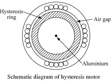
Ques.25. The drive motor used in a mixer-grinder is a (SSC-2018 Set-5)
- DC Motor
- Induction Motor
- Synchronous Motor
- Universal Motor
Answer.4. Universal Motor Explanation:-
Ques.26. The capacitors used in single-phase capacitor motors have no (SSC-2018 Set-5)
- Voltage Rating
- Dielectric Medium
- Polarity marking
- Definite Value
Answer.3. Polarity marking Explanation:- Electrolytic capacitors: Electrolytic capacitors normally have the smallest volume and cost for a given capacitance. These types of capacitors are mainly used in applications where a large value of capacitance in a small volume is required, such as the filter in a power supply. Electrolytic capacitors are very widely used in filters, time constant circuits, bypass. coupling-decoupling, smoothing, starting of A.C motor and power electronics applications. POLARIZED ELECTROLYTIC CAPACITORS Polarized capacitors are generally referred to as electrolytic capacitors These capacitors are sensitive to the polarity to which they are connected and will have one terminal identified as positive or negative. Polarized capacitors can be used in DC circuits only. These capacitors must be connected in the circuit as per the polarity marked on the capacitor. If they are connected in opposite polarity, the reversed electrolysis forms gas in the capacitor It becomes hot and may explode. The advantage of electrolytic capacitors is that they can have very high capacitance in a small case. NON-POLARIZED ELECTROLYTIC CAPACITORS A non-polar electrolytic capacitor can be thought of as being the same as having two polarized electrolytic capacitors in series, negative to negative, so the polarity of the voltage supplied is not important for the circuits continued operation. This capacitor is used as the starting capacitor for many small single-phase motors, as the run capacitor in many ceiling fan motors, and for low-power electronic circuits when a nonpolarized capacitor with a high capacitance is required. The AC electrolytic capacitor is made by connecting two wet-type electrolytic capacitors inside the same case, as shown in the figure. In the example shown, the two wet-type electrolytic capacitors have their negative terminals connected. When alternating current is applied to the leads, one capacitor will be connected to reverse polarity and become short. The other capacitor will be connected to the correct polarity and will form. During the next half-cycle, the polarity changes: it forms the capacitor that was shorted and shorts the other capacitor.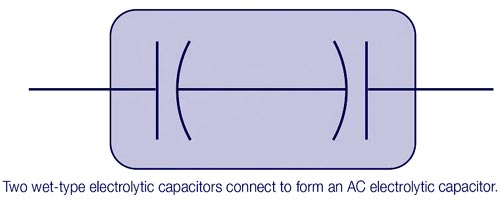
Ques.27. How will the total capacitance change, when two capacitors are connected in parallel? (SSC-2018 Set-5)
- The total capacitance increases
- The total capacitance decreases
- The mean value gives the new capacitance
- The total capacitance is found by the reciprocal equation
Answer.1. The total capacitance increases Explanation:- Capacitance in Parallel When two equal capacitors are connected in parallel, the plates of the individual capacitors, in effect, combine to form one capacitor representing total capacitance. Notice in Figure. that the effective plate area of the equivalent capacitor has doubled. Since an increase in plate area increases capacitance, it can be concluded that the total capacitance of the two capacitors in parallel is equal to the sum of the two capacitors. This direct relationship between total capacitance and capacitors in parallel is described bit this equation: CTotal = C1 + C2 Mathematically, The charge on a capacitor is given as Q = CV Where C is the capacitance V is the applied voltage In the parallel circuit, the voltage remains the same and the charge depends upon the capacitor size. Q1 = C1V Q2 = C2V Q = Q1 + Q2 CeqV = C1V + C2V Ceq = C1 + C2 Hence in the parallel plate capacitor, the capacitance increases.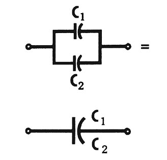
Ques.28. When the load on a reluctance motor is increased so that it cannot maintain synchronous speed the motor will (SSC-2018 Set-5, SSC-2016)
- Become unstable
- Draw excessive armature current and may burn out
- Fall out of synchronism and come to a standstill
- Run as an induction motor
Answer.4. Run as an induction motor Explanation:- It is a single-phase synchronous motor which does not require d.c. excitation to the rotor. Its operation is based upon the following principle: Whenever a piece of ferromagnetic material is located in a magnetic field, a force is exerted on the material, tending to align the material so that reluctance of the magnetic path that passes through the material is minimized. The motor runs up to slip speed as an induction motor, pulls into step with the rotating field by means of the reluctance torque and then operates as a synchronous reluctance motor. Working Principle The stator consists of a single winding called main winding. But single winding cannot produce a rotating magnetic field. So for production of rotating magnetic field, the must be at least two windings separated by the certain phase angle. Hence staler consists of an additional winding called auxiliary winding which consists of the capacitor in series with it. Thus there exists a phase difference between the currents carried by the two winding and corresponding fluxes. Such two fluxes react to produce the rotating magnetic field. The technique is called split phase technique of production of rotating magnetic field. The speed of this field is the synchronous speed which is decided by the number of poles for which stator winding is wound. The rotor carries the short-circuited copper or aluminum bars and acts as squirrel cage rotor of an induction motor. If an iron piece is placed in a magnetic field, it aligns itself in a minimum reluctance position and gets locked magnetically. Similarly, in the reluctance motor, the rotor tries to align itself with the axis of the rotating magnetic field in a minimum reluctance position. But due to rotor inertia, it is not possible when the rotor is at standstill. So rotor starts rotating near synchronous speed as a squirrel cage induction motor. When the rotor speed is about synchronous, stator magnetic field pulls the rotor into synchronism i.e. minimum reluctance position and keeps it magnetically locked. Then the rotor continues to rotate with a speed equal to synchronous speed. Such a torque exerted on the rotor is called the reluctance torque. Thus finally the reluctance motor runs as a synchronous motor. The resistance of the rotor must be very small and the combined inertia of Me rotor and the load should be small to run the motor as a synchronous motor. Note:- When the load on the synchronous motor increased than the speed of the reluctance motor decreases working as an induction motor Advantages The reluctance motor has the following advantages Limitations The reluctance motor has the following limitationReluctance Motor
Ques.29. A universal motor can run on (SSC-2018 Set-5)
- A.C. only
- D.C. only
- Either A.C. or D.C
- None of these
Answer.3. Either A.C. or D.C Explanation:- The universal motor is one which operates both on A.C and D.C supply. Its principle of operation is the same as that of a de series motor, i.e., force is created on the armature conductors due to the interaction between the main field flux and the flux created by the current-carrying armature conductors. The series wound DC motor is the only type of DC motor that works on AC although the efficiency of the motor is very poor. However, the Universal motor is constructed with few series fields turns, laminated armature and field circuits, low reluctance magnetic path, increased armature conductors and commutator segments by using low flux densities. This is done to minimize the adverse effects caused by high field reactance, eddy current, and Hysteresis Losses. We may consider a typical DC series motor or a DC shunt motor for operation on AC power supplies. It appears that such an operation is possible because reversing the line terminals to a DC motor reverses the current and magnetic flux in both the field and armature circuits. As a result, the net torque of the motor operating from an AC source is in the same direction. However, the operation of a DC shunt motor from an AC source is impractical because the high inductance of the shunt field causes the field current and the field flux to lag the line voltage by almost 90°. The resulting torque is very low. A DC series motor also fails to operate satisfactorily from an AC source because of the excessive heat developed by eddy currents in the field poles. In addition, an excessive voltage drop occurs across the series field windings due to high reactance. To reduce the eddy currents, the field poles can be laminated. To reduce the voltage loss across the field poles to a minimum, a small number of field turns can be used on a low reactance core operated at low flux density. A motor with these revisions operates on either AC or DC and is known as a universal motor. Universal motors in small fractional horsepower sizes are used in household appliances and portable power tools. Universal motors may be either compensated (distributed field) or uncompensated (concentrated field) type, the latter type being used for the higher speeds anal smaller output ratings (usually not exceeding 200 Watt only. CONCENTRATED-FIELD UNIVERSAL MOTORS A concentrated-field universal motor is usually a salient-pole motor with two poles and a winding of relatively few turns. The poles and winding are connected to give the opposite magnetic polarity. DISTRIBUTED-FIELD UNIVERSAL MOTORS The two types of distributed-field universal motors are the single-field compensated motor and the two-field compensated motor. The field windings of a two-pole, single-field compensated motor resemble the stator winding of a two-pole, split-phase AC motor. A two-field compensated motor has a stator containing the main winding and a compensating winding spaced 90 electrical degrees apart. The compensating winding reduces the reactance voltage developed in the armature by the alternating flux when the motor operates from an AC source. The armature of a typical universal motor resembles the armature of a typical D.C motor except that a universal motor armature is slightly larger for the same horsepower output. Operation In a series wound motor, the same current flows through field windings and armature, being connected in series with each other when the motor is connected to either DC or AC supply. The magnetic fields developed by the series field winding and armature currents react with each other and hence develop unidirectional torque. Since the armature and field are in series, the current is the same through them, and there is no time lag or phase displacement in the magnetic fields. The attraction and repulsion forces will nearly be the same if operated on DC or AC. Because these motors are series-wound, they operate at excessive speed at the no-load condition. As a result. they are usually permanently connected by gears to the devices being driven.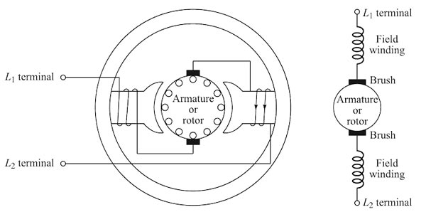
Ques.30. Which of the following motors has two separate windings on the motor? (SSC-2018 Set-5)
- Repulsion motor
- Repulsion induction motor
- Repulsion start induction run motor
- None of these
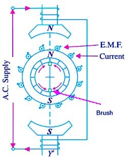
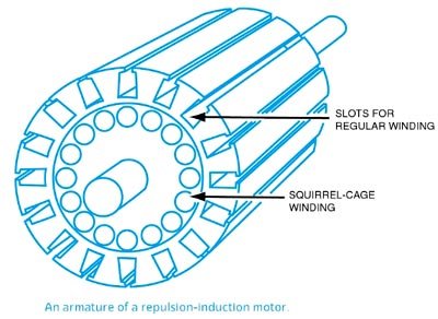
Answer.2. Repulsion induction motor Explanation:- A repulsion motor operates on the principle that like magnetic poles repel each other, not on the principle of a rotating magnetic field. The stator of a repulsion motor contains only a run winding very similar to that used in the split-phase motor. Start windings are not necessary. The rotor is actually called an armature because it contains a slotted metal-core with windings placed in the slots. The windings are connected to a commutator. A set of brushes makes contact with the surface of the commutator bars. The entire assembly looks very much like a DC armature and brush assembly. One difference, however, is that the brushes of the repulsion motor are shorted together. Their function is to provide a current path through certain parts of the armature, not to provide power to the armature from an external source. Operation Although the repulsion motor does not operate on the principle of a rotating magnetic field, it is an induction motor. When AC power is connected to the stator winding, a magnetic field with alternating polarities is produced in the poles. This alternating field induces a voltage into the windings of the armature. When the brushes are placed in the proper position, current Hows through the armature windings, producing a magnetic field of the same polarity in the armature. The armature magnetic field is repelled by the stator magnetic field, causing the armature to rotate. Repulsion motors will contain the same number of brushes as there are stator poles. Repulsion motors are commonly wound for four, six, or eight poles. Repulsion Induction Motor It works on the combined principle of repulsion and induction. The construction of the stator of this type of motor is similar to that of a repulsion motor, i.e., the main stator winding of a single-phase induction motor. In the rotor, there are two separate windings. One winding is similar to the rotor winding of a repulsion motor i.e usual d.c winding connected to the commutator. The other winding is of squirrel-cage type, placed below the repulsion-motor type winding. The behavior of the repulsion induction motor is, therefore, the combination of the behavior of repulsion motor and an induction motor. Under starting condition, the very little current will flow through the inner squirrel-cage winding since the reactance of the squirrel-cage winding which is placed deep into the rotor slot is very high. As the rotor picks up speed, the frequency of the rotor induced emf and hence the rotor reactance will decrease. More current will flow in the rotor squirrel-cage winding. The motor will work as a combination of repulsion and induction motor.