Ques.61. In a single-phase induction motor, the speed-sensitive centrifugal switch is connected in ____winding (SSC-2014)
Parallel with the main
Series with main
Parallel with starting
Series with starting
Answer.4. Series with starting
Explanation:-
The centrifugal switch is connected in series with the starting winding. The primary function of the centrifugal switch is to produce rotating flux in conjunction with the main winding at the time of starting. When the motor has started and reaches nearly 75% of synchronous speed, it produces its own rotating field from the cross-field effect. The starting winding now has no function to perform and is removed from the circuit by a centrifugally operated switch.
Ques.62. At starting, the current through the starting winding (Is ) of single-phase induction motor (SSC-2014)
Lags V by 90°
Leads V by 90°
Nearly in phase with V
Leads V by 75°
Answer.3. Nearly in phase with V
Explanation:-
In single-phase induction motor mainly there are two types of windings main winding or running winding and auxiliary winding or starting winding.
The auxiliary winding or running winding carries a series resistance such that its impedance is highly resistive on the other hand the main winding or running winding is highly inductive in nature.
As we know that if the circuit is highly resistive the current and voltage are in phase with each other therefore current through starting winding in a single-phase induction motor is almost in phase with the voltage.
Ques.63. In a single-phase induction motor at the start, the two revolving fields produce (SSC-2014)
Unequal torques in the rotor conductors
No torque in the rotor conductor
Equal and opposite torques in the rotor conductors
Equal torques in the same direction in the rotor conductors
Answer.3. Equal and opposite torques in the rotor conductors
Explanation:-
The working principle of an ac machine is primarily “one field following another field”. In the case of a multiphase induction motor, there will be a virtual rotating magnetic field. But considering the case of a single-phase induction motor, it’s only a pulsating field that is produced and not a rotating one. This can also be explained on the basis of ‘DOUBLE REVOLVING FIELD THEORY‘, which goes as follows: Current through a conductor produces a flux. This flux can be resolved into 2 components, each one rotating in the opposite directions at the same speed(slip).
As a result, the net flux is zero, the induced current in the rotor conductors is zero, resulting in zero torque. So, a single-phase induction motor is not self-starting.
Ques.64. The single-phase Induction Motor(IM) which does not have centrifugal switch is (SSC-2013)
Capacitor start single phase IM
Resistance split single phase IM
Capacitor start capacitor run single phase IM
Permanent capacitor run single phase IM
Answer.4. Permanent capacitor run single phase IM
Explanation:
Permanent capacitor run single phase IM
Permanent capacitor single phase IM
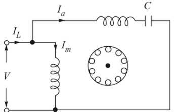
In permanent capacitor run, single phase Induction motor a single capacitor is connected in series with the auxiliary winding permanently thus the winding and the capacitor remains energised for both starting and running purpose.
Therefore permanent capacitor motor behaves virtually as the two-phase motor which is running on single-phase supply.
The starting torque of this motor is very low as compared to the capacitor start motor and capacitor start run motor.
Since the same capacitor is used for the starting and running purpose, therefore, it is called as Permanent capacitor run single phase IM
Ques.65. If the centrifugal fuse of a single-phase resistance split induction motor does not operate after starting of the motor, the motor (SSC-2013)
Will run above normal speed
Will run below normal speed
Will draw a very small current
Will draw very high current and over-heated
Answer.4. Will draw very high current and over-heated
Explanation:
If the centrifugal switch is failed to open then the starting winding will draw very high current and it may burn the winding.
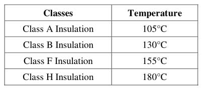
Ques.66. Maximum temperature limit for class F insulation is (SSC-2012)
130°C
120°C
105°C
155°C
Answer.4. 155°C
Explanation:-
The electrical insulation system is sometimes referred to as insulation class or thermal classification. The different classes are defined by NEMA which is given below
Ques.67. AC series motors are built with as few turns as possible to reduce (SSC-2012)
Flux
Reactance
Iron losses
Speed
Answer.2. Reactance
Explanation:-
Why an AC series Motor are Built with few turns?
The AC series motor operates on either AC or DC circuits. When an ordinary DC series motor is connected to an AC supply, the current drawn by the motor is low due to the high series-field impedance. The result is low running torque. To reduce the field reactance to a minimum, AC series motors are built with as few turns as possible.
The decrease in the number of turns of the field winding reduces the load torque, i.e., if field turns to decrease, its MMF decreases and then flux, which will increase the speed, and hence the torque will decrease. But in order to maintain constant load torque, it is necessary to increase the armature turns proportionately.
If the armature turns increase, the inductive reactance of the armature would increase, which can be neutralized by providing the compensating winding.
Ques.68. Based on revolving field theory, the forward and backward frequencies of the rotor emf of a 4-pole, 50 Hz, single-phase induction motor when running at 1300 rpm in the same direction of the forward field are respectively. (SSC-2012)
6.67 Hz, 93.33 Hz
107.69 Hz, 7.69 Hz
93.33 Hz, 6.67 Hz
7.69 Hz, 107.69 Hz
Answer.3. 93.33 Hz, 6.67 Hz
Explanation:-
Forward field slip Speed
SF = (Ns -Nr)/Ns
Synchronous speed Ns = 120f/p = 120×50/4 = 1500
(1500 – 1300)/1500 = 0.133Hz
Rotor frequency due to forward field = SF x F = 0.133 x 50 = 6.67 Hz
Backward slip of an induction motor
Sb = (2 – Sf) = 2 – 0.133 = 1.87 Hz
Rotor frequency due to Backward field = Sbx F = 1.87 x 50 = 93.35Hz.
Ques.69. A universal motor is a _______ motor. (SSC-2012)
Series
Single-phase induction
Synchronous
Shunt
Answer.1. Series
Explanation:-
The universal motor is so named because it is a type of electric motor that can operate on AC or DC power. It is a commutated series-wound motor where the stator’s field coils are connected in series with the rotor windings through a commutator. It is often referred to as an AC series motor.
Ques.70. Which of the following motors can work satisfactorily on both AC and DC? (SSC-2012)
Synchronous motor
Series motor
Shunt motor
Induction motor
Answer.2. Series motor
Explanation:-
The single-phase series motor is a commutator-type motor. If the polarity of the line terminals of a dc series motor is reversed, the motor will continue to run in the same direction. Thus, it might be expected that a dc series motor would operate on alternating current also.
A series motor that is specifically designed for dc operation suffers from low efficiency, poor power factor, sparking in brushes.
In order to overcome these difficulties, the following modifications are made in a D.C. series motor.
The field core is made up of low hysteresis loss material and is laminated to reduce eddy current loss. The field winding is provided with the small number of turns to reduce iron losses and to increase commutation and reduce armature reaction compensating winding is used.
Ques.71. If the speed of a universal motor in AC operation is Nac and in DC operation is Ndc (and I = current, V = supply voltage, r = resistance, X = reactance, cosΦ = power factor) then the speed ratio (SSC-2011)
Nac/Ndc = (cosΦ – IX/V)/(1 – IR/V)
Nac/Ndc = (1 – IR/V)/ (cosΦ – IX/V)
Nac/Ndc = (1 – IR/V)/ (cosΦ – IR/V)
Nac/Ndc = (cosΦ – IR/V)/(1 – IR/V)
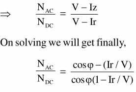
Answer.4. Nac/Ndc = (cosΦ – IR/V)/(1 – IR/V)
Explanation:-
For AC supply,
EAC = V – I(R + jX)
For DC supply,
EDC = V – IR
From both the above equation
EAC/EDC = (V – IZ)/(V – IR)
Where power factor cosφ = R/Z
Since In universal motor EMF is directly proportional to the motor speed hence
EAC = NAC & EDC = NdC
Ques.72. An electric motor may give noise due to (SSC-2010)
Magnetic effect
Defective Bearing
Cooling Air
All of the above
Answer.4. All of the above
Explanation:-
Air gap: The air gap can also cause noise. The gap between the rotor and the stationary poles is important in noise production. When the air gap is too small, the stator teeth can become over saturated and the motor noise will increase.
Distribution of Magnetic Flux: The distribution of the field flux makes a great deal of difference in the quietness of an electric motor. The quietness of motor operation depends on the strength of the magnetic flux and how it is distributed. For example, the permanent split capacitor motor has two windings and thus has a more even flux distribution. It is less noisy than the split-phase motor.
Bearing: Bad Bearings is also a source of electrical noise. Sleeve bearings often come installed in small motors. They provide bearings that are, in a general-purpose system, smooth operating. The sleeve bearing is quieter than the ball bearing. Bali bearings have less friction but are more susceptible to damage when bumped on the end. Larger motors use roller bearings while very large motors utilize a forced-oil bearing
Ques.73. A 4-pole, the 3-phase induction motor is running at 4% slip at full load. If the speed of the motor is 750 rpm, the supply frequency is (SSC-2010)
50/3 Hz
26 Hz
50 Hz
60 Hz
Answer.2. 26 Hz
Explanation:-
Nr = 750 RPM
s = 0.04
Since Nr = Ns(1 – s)
= 750 = Ns(1 – 0.04)
Ns = 781.25 RPM
Now synchronous speed of motor
Ns = 120f/P
781.25 = 120f/4
f = 26.04 Hz
Ques.74. A single-phase motor is made-starting by the addition of a (SSC-2010)
Running winding
Starting winding
Electric starter
Auto-transformer
Answer.2. Starting winding
Explanation:-
In order for an induction motor to be rotated, there should be rotating magnetic. In the case of single-phase motor during the positive half cycle, the rotor will rotate in one direction and in the negative half cycle, it rotates opposite to that. So the net torque developed is zero and hence single phase induction motor is not self-starting.
In order to self-start a single-phase induction motor one must create a rotating magnetic field on the stator. Hence, the single-phase motor needs an auxiliary winding which produces two magnetic fields displaced in time which provides a magnetic field and used to create the torque needed to start a single-phase induction motor
Ques.75. A 1-Φ induction motor is running at N-rpm. Its synchronous speed is Ns. If its slip with respect to forward field is s, what is the slip with respect to the backward field? (SSC-2009)
s
-s
(1 – s)
(2 – s)
Answer.4. (2 – s)
Explanation:-
Slip with respect to forward field
S = (Ns – N)/Ns = 1 – N/Ns
Since the backward rotating flux will rotate opposite to the stator hence the sign rotor speed N will be changed
Sb = (Ns – [-N])/Ns = 1 + N/Ns
Adding both the equation
S + Sb = (1 – N/Ns) + (1 + N/Ns)
Sb = 2 – s
Ques.76. The direction of rotation of 3-Φ induction motor is clockwise when it is supplied with the 3-Φ sinusoidal voltage having a phase sequence of A-B-C. For counterclockwise rotation, the phase sequence of the power supply should be (SSC-2009)
B-C-A
A-C-B
C-A-B
Any of the above
Answer.2. A-C-B
Explanation:-
The direction of rotation of a 3 phase induction motor can be reversed by interchanging any two of the three motor supply lines.
The phase sequence of the three-phase voltage applied to the stator winding is A-B-C. If this sequence is changed to A-C-B, it is observed that the direction of rotation of the field is reversed i.e., the field rotates counterclockwise rather than clockwise. However, the number of poles and the speed at which the magnetic field rotates remain unchanged.
Ques.77. In repulsion motor direction of rotation of motor (SSC-2009)
Same as that of brush shift
Independent of brush shift
Opposite to that of brush shift
None of the above
Answer.1. Same as that of brush shift
Explanation:-
The direction of rotation is determined by the position of the brushes with respect to the magnetic field of the stator.
If the brushes are shifted clockwise from the main magnetic axis, the motor will rotate in a clockwise direction.
If the brushes are shifted counterclockwise from the main magnetic axis, the motor will rotate in a counter-clockwise direction
For SSC JE 3-Phase Induction Motor Solved Questions (2009 – 2018) Click Here
For SSC JE Measurement & Instrumentation Solved Questions (2009 – 2018) (Part-2) Click Here
For SSC JE Measurement & Instrumentation Solved Questions (2009 – 2018) (Part-1) Click Here
For SSC JE Basic Electrical Questions Solved (2009 – 2018) (Part-3) Click Here
For SSC JE Basic Electrical Questions Solved (2009 – 2018) (Part-2) Click Here
For SSC JE Basic Electrical Questions Solved (2009 – 2018) (Part-1) Click Here
For SSC JE Electrical Transformer Questions Solved (2009 – 2018) Click Here