Ques 11. The efficiency of a 100 KVA transformer is 0.98 at full as well as half load. For this transformer at full load the copper loss
Is less than the core loss
is equal to core loss
is more than core loss✔
All the above
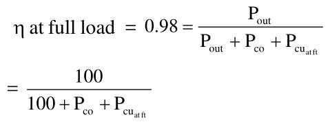
η at full load = η at half load = 0.98
η at full load of the transformer
Pco + Pcufl = 2.0408
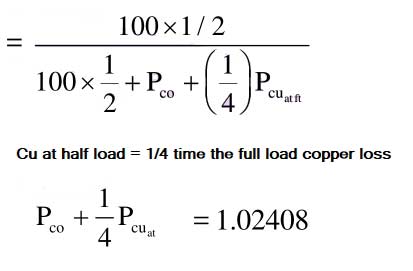
η at half load =
Solving the equation
Pco = 0.6802 KW
Pcufl = 1.3605 KW
Pcufl > Pco
Ques 12. Which of the following will improve the mutual coupling between primary and secondary circuits?
Transformer oil of high break down voltage
High reluctance magnetic core
Winding material of high resistivity
Low reluctance magnetic core✔
Magnetic reluctance, or magnetic resistance, is a concept used in the analysis of magnetic circuits. It is analogous to resistance in an electrical circuit, but rather than dissipating electric energy it stores magnetic energy.
Low the reluctance, less the opposition to flux therefore more flux can pass through the transformer core.
Therefore the transformer core is made of magnetic steel that has high permeability (low reluctance) to the magnetic flux.
Ques 13. High leakage transformers are of
Small voltage-ampere rating✔
High voltage-ampere rating
High voltage rating
Low voltage rating
Leakage transformers are transformers where the magnetic flux of the secondary is loosely coupled to the flux of the primary. This loose coupling ensures that the transformer can withstand short circuit conditions.
The output and input current of the leakage transformer is low enough to prevent thermal overload under load condition even if the secondary is shorted. Leakage Transformers are also known as Stray field Transformers.
Leakage transformers are used for arc welding and high-voltage discharge lamps (neon lights and cold cathode fluorescent lamps, which are series-connected up to 7.5 kV AC). They act as both a voltage transformer and a magnetic ballast. Other applications are short-circuit-proof extra-low voltage transformers for toys or doorbell installations.
Ques 14. The starting torque of a 3-phase induction motor varies as
V2✔
V
√V
1/V
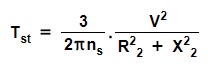
Starting torque if 3 phase induction motor is given as
Where ns = synchronous speed in r.p.s i.e Ns/60
V = Rotor voltage
R2 = Rotor resistance
X2 = Rotor Reactance
∴ Tst ∝ V2
So starting torque of a 3-phase induction motor is directly proportional to V2
Ques 15. In a 3-phase induction motor, the mechanical power developed, in terms of air gap power Pg is
(1 – s)Pg✔
Pgs
Pg/(1 – s)
Pg/s
Let Pg = Air gap power
Pcu = Rotor copper loss = sPg
Pm = Mechanical power or Gross power output
Pm = Air gap power – Rotor copper loss
= Pg – sPg
Pm = (1 – s)Pg
Ques 16. The negative phase sequence in a 3-phase synchronous motor exists when the motor is
Underloaded
Overloaded
Supplied with Unbalanced voltage✔
Hot
Negative phase sequence current in Synchronous motor
Negative sequence currents are produced because of the unbalanced voltage in the power system.
The flow of negative sequence currents in electrical machines (generators and motors) is undesirable as these currents generate high and possibly dangerous temperatures in a very short time.
Phase current and voltage in the three-phase system can be represented in the form of three single-phase components.
Positive sequence components, Negative sequence components, and Zero sequence components.
Positive sequence currents exist during the balanced load condition.
Ques 17. A center zero ammeter connected in the rotor circuit of a 6-pole, 50 Hz induction motor makes 30 oscillations in one minute. The rotor speed is
670 RPM
1000 RPM
990 RPM✔
1030 RPM
The ammeter has 30 oscillations in one minute. So, rotor current has a frequency
Ques 18. The permissible variation of frequency in power system Ps is
± 1%
± 3%✔
± 5%
± 10%
According to CENTRAL ELECTRICITY REGULATORY COMMISSION OF INDIA
Ideal Range of frequency variation
f = 50 ± 1%
49.5 to 50.5 Hz
Practical permissible Range of frequency variation
f = 50 ± 3%
48.5 to 51.5 Hz
The grid frequency should be maintained at 48.6 Hz. and above at all times.
Ques 19. For cooling large size generators hydrogen is used because
It offers reduced fire risk
It is light in weight
It is of high thermal conductivity
All of the above✔
Why is hydrogen used for Alternator cooling?
Hydrogen is the least expensive, has less weight, has high thermal conductivity, less density, and has less viscosity. Less weight, less density & less viscosity are attributed to its flow rate. High thermal conductivity helps in better heat exchange. The least expensive help in balance sheets, more power in fewer investments.
In order to reduce the high temperature of the alternator hydrogen gas is used as a coolant. The coolant, Hydrogen gas is allowed to flow in a closed cyclic path around the rotor. Heat exchange takes place and the temperature of hydrogen gas increases, for better cooling of the rotor in the next cycle it has to be cooled.
Cooling of hydrogen gas is done by passing it through heat exchangers generally constituted with water. Now Hydrogen gas after cooling is allowed to pass through driers ( mainly silica gel which absorbs moisture) and allowed to pass again through the rotor.
Ques 20. The connected load of a consumer is 2 kW and his maximum demand is 1.5 kW. The demand factor of the consumer is
0.75✔
0.375
1.33
1
Demand factor is the ratio of the sum of the maximum demand of a system (or part of a system) to the total connected load on the system (or part of the system) under consideration.