Ques 21. To meet the reactive power requirements of load centers usually
Shunt capacitors are used✔
Series capacitors are used
Shunt reactors are used
Tap changing transformers are used
Loads in electric power systems consume real power (MW) and reactive power (MVAr). Because most loads lag and the line reactance is much greater than the line resistance, switching shunt capacitors across the line will increase the voltage by reducing the inductive drawn.
Unlike real power (MW), the generation of reactive power (MVAr) at power plants and transmission of the reactive power over long distances to loads is not economically feasible.
Shunt capacitors are widely used in primary distribution to supply reactive power to loads. They draw leading currents that offset the lagging component of currents in inductive loads. They can also reduce line losses and improve voltage regulation
Ques 22. The power factor will be leading in the case of
Dielectric heating✔
Resistance heating
Induction heating
All the above
Dielectric heating (also called High-frequency capacitive heating) is employed for heating insulators like wood, plastics, ceramics, etc.
When a capacitor is subjected to a sinusoidal voltage, the angle between the current and voltage is al slightly less than 90°with the result that there is a small in-phase component of the current which produces power loss in the dielectric of the capacitor.
At the frequency of 50 Hz, such loss may be small enough to be negligible but at a high frequency, the loss becomes large enough to heat the dielectric. It is this loss that is utilized in heating the dielectric.
The overall efficiency of dielectric heating la about 60 percent.
Ques 23. Which instrument has the lowest resistance?
An ideal Ammeter has zero resistance. An Ammeter, connected in series, is supposed to have as little current as possible to indicate the reading otherwise, the indication will be wrong by a large margin. This means it must allow as much as possible current to pass through. Thus, by definition, it should possess a resistance as close to zero as possible.
Ques 24. The moving coil in a dynamometer wattmeter is connected
In series with the fixed coil
Across the supply✔
In series with the load
Anyone of the above
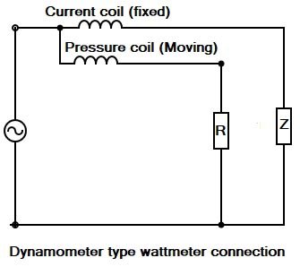
A dynamometer-type wattmeter is most commonly employed for the measurement of power in a.c as well as d.c circuits. It is based on the principle that mechanical force exists between two current-carrying conductors. It essentially consists of two coils, namely a fixed coil and a moving coil.
These two coils are connected in different arrangements. The fixed coils or current coils are connected in series with the load and the moving coil is connected across the Voltage and therefore, carries a current proportional to the voltage. Since the moving coil carries a current proportional to the voltage, it is called the ‘pressure coil’ or ‘voltage coil’ of the wattmeter.
The current coils which are fixed are divided into two halves. The fixed coils are wound with heavy wire (fewer turns) as they have to offer small resistance to the load current flowing through them.
The reason for dividing the current coil into two halves is simply to produce the uniform magnetic field for the moving coil. The ‘pressure coil’ which is free to move is mounted on a pivoted spindle and carries a pointer.
Ques 25. In a series R-L-C circuit, susceptance is equal to
1/X
1/R
R/Z2
X/Z2✔
In electrical engineering, susceptance (B) is the imaginary part of admittance, whereas the real part is conductance. The inverse of admittance is impedance, where the imaginary part is reactance and the real part is resistance.
The general equation defining admittance is given by
where
Y is the admittance, measured in Siemens.
G is the conductance, measured in Siemens.
j is the imaginary unit and
B is the susceptance, measured in Siemens.
The admittance (Y) is the inverse of the impedance (Z)
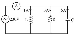
Ques 26. The current read by the ammeter A in the AC circuit shown in the following figure is
9A
5 A✔
3 A
1 A
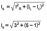
Current for a Parallel RLC Circuit
Is = 5A
Ques 27. A 4-pole generator with 16 coils has a two-layer lap winding. The pole pitch is
32
16
8✔
4
Pole pitch = slots/pole
Pole pitch = slots/pole
Number of commutator segments = 16
Number of conductors or coil side = 16 x 2 = 32
Pole pitch = 32/4 = 8
Ques 28. Two coupled coils with L1 = L2 = 0.6H have the coupling coefficient of K = 0.8. The turn ratio N1/N2 is
4
2
1✔
0.5
The self-inductance is given as
L = μN2A/I
L ∝ N2
where
N is the number of turns of the solenoid
A is the area of each turn of coil
l is the length of the solenoid
and μ is the permeability constant
L1/L2 = N21/N22
0.6/0.6 = N21/N22
N1/N2 = 1
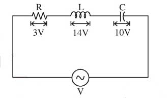
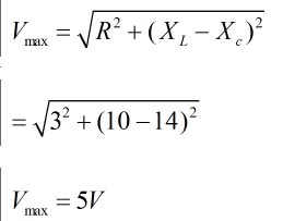
Ques 29. The voltage across the various elements is marked, as shown in the figure given below. The maximum input voltage is
Ques 30. The principle of dynamically induced emf is utilized in
Choke
Transformer
Thermocouple
Generator✔
In dynamically induced emf the magnetic field system is kept stationary, and the conductor is moving, or the magnetic field system is moving, and the conductor is stationary thus by following either of the two processes the conductor cuts across the magnetic field, and the emf is induced in the coil. Hence the emf induced in a coil due to the relative motion of the conductor and the magnetic field is called dynamically induced emf.
Dc generator works on the principle of dynamically induced emf. Whenever a conductor cuts magnetic flux, dynamically induced e.m.f. is produced in it according to Faraday’s Laws of Electromagnetic Induction. This e.m.f. causes a current to flow if the conductor circuit is closed