Ques 21. Differential relays are used to protect the equipment against
Internal fault
Reverse current
Overvoltage
Overcurrent✔
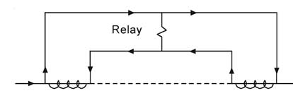
The differential relay works on the principle of comparison between the phase angle and magnitude of two or more similar electrical quantities. Most differential relay applications are of the current differential type. The simplest example of such an arrangement is shown in Figure.
The system element being protected might be a part of a circuit, a winding of a generator or a transformer or a portion of a bus, etc. A current transformer is shown on each side of the protected zone. The secondary of the CTs are interconnected and an over-current relay coil is connected across the CT secondary circuit.
If the two CTs having the same ratios are connected properly, their secondary currents will merely circulate between the two CTs. No current will flow through the relay coil and thus, it will not operate.
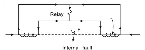
But when a fault takes place anywhere between the CTs, the phasor sum of the CT secondary currents will flow through the differential relay coil which will operate. The differential current flows whenever the current entering into the zone is not equal to the current leaving the zone. This is shown in Figure
Differential relays are very sensitive to the faults occurring within the zone of protection but they are least sensitive to the faults that occur outside the protected zone.
Ques 22. Skin effect exists only in
Low voltage dc overhead transmission
High voltage dc overhead transmission
The cable carrying dc current
AC transmission✔
The non-uniform distribution of electric current over the surface or skin of the conductor carrying a.c is called the skin effect. The skin effect is directly proportional to the frequency of the current flowing through the conductor because on increasing frequency reactance offered to its flow will increase and thus a larger amount of current will try to flow more near to the surface (skin effect).
Factors affecting skin effect
Frequency – The skin effect increases with the increase in frequency.
Type of material – Skin effect increase with the increase in the permeability of the material (Permeability is the ability of the material to support the formation of the magnetic field).
Diameter – It increases with the increase in the diameter of the conductor.
The shape of the conductor – Skin effect is more in the solid conductor and less in the stranded conductor because the surface area of the solid conductor is more.
Ques 23. For a 3-phase, 4-pole, 50 Hz synchronous motor the frequency, no. of poles, and the load torque are all halved. The motor speed will be
375 RPM
75 RPM
1500 RPM✔
3000 RPM
Speed of Synchronous Motor
Ns = 120f1/P
f1 = 50 Hz
P1 = 4
Now the frequency and no of poles are halved
f1 = 25 Hz
P1 = 2
= 120 x 25/2 = 1500 RPM
Ques 24. The making current of 3-phase breaker with rating 2000 MVA, 33kV will be
35 kA
50 kA
70 kA
89 kA✔
The breaking capacity of a circuit breaker is generally expressed in MVA, For three-phase circuit breaker it is given by
Breaking Capacity = √3 x rated voltage in kV x Rated current in KA
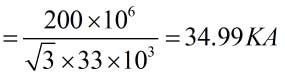
Rated current in KA = (Breaking capacity)/(√3 x rated voltage in kV)
Making current = 2.55 x Symmetrical breaking current
= 2.55 x 34.99 = 89.22 KA
Ques 25. A transformer is working at its full load and its efficiency is also maximum. The iron loss is 1000 watts. Then, its copper loss at half of the full load will be
250 watt✔
300 watt
400 watt
500 watt
At maximum efficiency Iron loss = copper loss = 1000 W
The copper loss at half load will be one-fourth times of full load copper loss. It is given by
Copper loss = X2 × copper loss at full load
Where
X stands for loading condition of the transformer
So for half loading copper loss will be
= (0.5)2 × 1000 w
= 250 W
Ques 26. Dielectric heating is also called
RF heating✔
Infrared heating
Surface heating
Eddy current heating
Dielectric heating, also known as electronic heating, RF (radio frequency) heating, and high-frequency heating, is the process in which a high-frequency alternating electric field, or radio wave or microwave electromagnetic radiation heats a dielectric material. At higher frequencies, this heating is caused by molecular dipole rotation within the dielectric.
Ques 27. Voltage drop is the main consideration while designing a
Feeder
Distributor✔
Service Main
All of the above
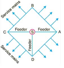
A distributor is a conductor from which tappings are taken for supply to the consumers.In fig, AB, BC, CD, and DA are the distributors. The current through a distributor is not constant because tappings are taken at various places along its length.
While designing a distributor, voltage drop along its length is the main consideration it also depends upon the nature of load and also on feeding, whether it is fed at one or both ends. The statutory limit of voltage variations is ± 6% of the rated value at the consumers’ terminals.
Ques 28. Laboratory wattmeters are
Induction type
Moving Iron Type
Electrostatics type
Electro-Dynamometer✔
A current measuring instrument that did not depend on the vagaries of magnetic materials was the electrodynamometer. This measured the forces between current-carrying conductors, so it was really only suitable for high current work. Being very reliable, however, it was frequently used in laboratories and for calibrating other instruments.
The meter is mechanically damped by means of aluminum vanes that move in enclosed air chambers. Although very accurate, electrodynamometer-type meters do not have the sensitivity of the D’Arsonval-type meter movement. For this reason, you will not find them used outside of the laboratory environment to a large extent.
Ques 29. An electric motor may give noise due to
Magnetic effect
Defective Bearing
Cooling Air
All of the above✔
Air gap: The air gap can also cause noise. The gap between the rotor and the stationary poles is important in noise production. When the air gap is too small, the stator teeth can become oversaturated and the motor noise will increase.
Distribution of Magnetic Flux: The distribution of the field flux makes a great deal of difference in the quietness of an electric motor. The quietness of motor operation depends on the strength of the magnetic flux and how it is distributed. For example, the permanent split capacitor motor has two windings and thus has a more even flux distribution. It is less noisy than the split-phase motor.
Bearing: Bad Bearings is also a source of electrical noise. Sleeve bearings often come installed in small motors. They provide bearings that are, in a general-purpose system, smooth operating. The sleeve bearing is quieter than the ball bearing. Bali bearings have less friction but are more susceptible to damage when bumped on the end. Larger motors use roller bearings while very large motors utilize a forced-oil bearing
Ques 30. Which of the following motor is used in household refrigeration?
Synchronous Motor
D.C shunt Motor
3- Phase Induction motor
1- phase induction motor✔
In a refrigerator, an Electric motor is used for compression which requires high torque. Single Phase Induction Motor is perfectly suited for this purpose. So a brushless, capacitor start/induction run, ‘ squirrel cage type’ motor is used in household refrigerators.
The rotor of the motor is a squirrel cage design, meaning aluminum bars are used instead of the conventional copper conductor.