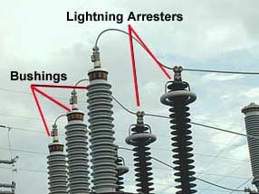
A lightning arrester is a device used in electrical power systems and telecommunications systems to protect the insulation and conductors of the system from the damaging effects of lightning.The arrester provides a low-impedance path to ground for the current from a lightning strike or transient voltage and then restores to normal operating conditions.
Lightning arresters are two-terminal devices in which one terminal is connected to the power line, and the other is connected to the ground. The path from line to ground is of high resistance that it is normally open. However, when lightning, which is a very high voltage, strikes a power line, it causes conduction from line to ground. Thus, voltage surges are conducted to the ground before the flashover between the lines occurs. After the lightning surge has been conducted to ground, the valve assembly then causes the lightning arrester to become nonconductive once more.
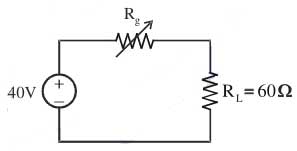
Ques 32. If Rg in the circuit shown in figure is variable between 20Ω and 80Ω then maximum power transferred to the load RL will be
15 W✔
13.33 W
6.67 W
2.4 W
R g = (20Ω to 80Ω)
Rg should be minimum to transfer maximum power to the load therefore we take
Rg = 20Ω
Hence I = V/(Rg + RL)
I = 40/80 = 0.5 A
Power transferred = I2RL
= (0.5)2 x 60 = 15 W
Ques 33. The knowledge of diversity factor helps in computing
Plant capacity✔
Average Load
Units Generator
Peak Demand
Diversity factor = Sum of individual peak demand/ Station peak demand.
Diversity helps in computing peak demand thus improving load factor and economic operation of the power plant. The diversity factor can be equal or greater than 1. If the value of the diversity factor is greater than 1, then it is a good diversity factor, and 1.0 represents a poor diversity factor.
Ques 34. Distribution transformers are designed to have maximum efficiency nearly at
100% of full load
50-70% of full load✔
25% of full load
10% of full load
Distribution transformers are used for lower voltage distribution networks as a means to end user connectivity. (11kV, 6.6 kV, 3.3 kV, 440V, 230V) and are generally rated less than 200 MVA. Distribution transformers depend on the typical load cycle for which it has to supply power. Definitely Core the design will be done to take care of peak load and as well as all-day-efficiency. It is a bargain between these two points.
The distribution transformer is used for the distribution of electrical energy at low voltage as less than 33KV in industrial purpose and 440v -220v in domestic purpose. It works at low efficiency at 50-70%(due to variation in load), small size, easy in installation, having low magnetic losses & it is not always fully loaded.
Ques 35. Electronic switching are becoming more and more popular because of
Noiseless operation
Long Life
Smaller size and weight
All the above✔
Advantages of Electronic Switching
Electronic switches are extremely fast.
They occupy very small space.
Cost of an electronic switch is much lower than that of a mechanical switch
Electronic switches are available in integrated-circuit form.
Complex logic functions are easily realized using electronic switches
Noiseless operation at high efficiency owing to the absence of moving part.
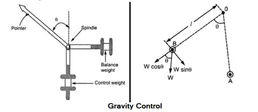
Ques 36. The controlling torque in gravity controlled meter is proportional to
cosθ
sinθ✔
tanθ
θ
Gravity Control Meter
For controlling torque Gravity control meter is used, especially in cheap control meter. This type of control consists of a small weight attached to the moving system whose position is adjustable. This weight produces a controlling torque due to gravity. This weight is called control weight.
The Fig. shows the gravity control system. At the zero position of the pointer, the controlling torque is zero. If the system deflects, the weight position also changes. The system deflects through an angle θ. The control weight acts at a distance l from the centre. The component W sinθ of this weight tries to restore the pointer back to the zero position. This is nothing but controlling torque Tc
Tc = Ksinθ
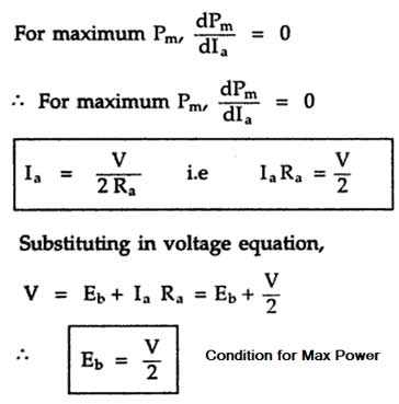
Ques 37. The condition for a maximum power output from dc motor is
Eb =V
Eb = V/2✔
Eb = 0
Eb = V/√2
Condition for maximum power
Mechanical power developed in the motor is
P = EbIa = VIa – Ia2Ra
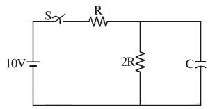
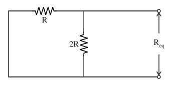
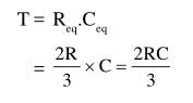
Ques 38. Time constant of the network shown in figure is
Ques39. A 2 kVA transformer has iron loss of 150 W and full load copper loss of 250 W. The maximum efficiency of the transformer will occur when the total loss is
500 W
400 W
300 W✔
275 W
When variable loss becomes equal to the constant loss, efficiency is maximum.
Losses = Pi + Pc
Since copper loss is a variable loss therefore
Losses = Pi + Pi = 2pi
Thus at maximum efficiency of this transformer total loss
= 150 x 2 = 300 W
Ques 40. While starting synchronous motor its field winding should be
Kept Open
Connected to DC source
Connected to AC source
Kept short-circuited✔
In the case of an induction motor, the field winding is permanently short-circuited by end rings.
In a Synchronous motor, the rotor winding is supplied with DC excitation. Now, if we eliminate the DC excitation, there are two ends of the wire available.
Let short-circuit the two ends of the wire (or connect the two ends of variable resistors).
Now the rotor winding of the synchronous motor is analogous to that of an induction motor.
Therefore if we short-circuit the field winding of a synchronous motor then it will behave as an induction motor.