Ques 41. During arc extinction SF6 circuit breaker
Decomposed into SF4 and SF2✔
Decomposed into S and F ions
Reduced to SF2
Oxidized
During Arc extinction process SF6 is decomposed into atoms, electrons and ions. These atomic components do not recombine completely to form the original SF6 gas on cooling. They form low molecular gaseous sulfur fluorides and compounds with the contact metals principally SF4 and SF2, together with a small amount of S2, F2, S, and F.
Ques 42. Sparking between the contacts of a circuit breaker can be reduced by inserting
A capacitor in parallel with the contacts✔
A capacitor in series with the contacts
A resistor in the line
A reactor in the line
Switch arc essentially can be treated as a capacitor with the contacts as the plate. When the contacts are far apart there is a very small capacitance, but as the switch closes the capacitance increases rapidly causing a significant change in the amount of charge stored in the “plates” this current surge is the source of the spark.
When capacitors are connected together in parallel the total or equivalent capacitance, CT in the circuit is equal to the sum of all the individual capacitors added together. This parallel capacitor will create an alternate current path for transient currents rather than jumping the closing gap of the switch contacts, the current will take the path of least resistance into the capacitor. Therefore the low value of surge occurs hence no arc will generate.
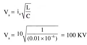
Ques 43. If the inductance and capacitance of a power system are respectively 1H and 0.01μF and the instantaneous value of interrupted current is 10A, then the voltage across the breaker contacts will be
50 kV
57 kV
60 kV
100 kV✔
Characteristic Impedance of the line
Z = √L/C
and Z = V/I
Ques 44. Which of the following materials for the heating element should be selected if a furnace is to be used for heating upto temperature around 1500°C.
Eureka
Kanthal
Platinum-molybdenum carbon compound✔
Nichrome
Melting point of Eureka is 1221 to 1300 °C
Melting point of Kanthal is 1,425 °C
Melting point of Nichrome is 1400 °C
Molybdenum compounds (about 14% of world production of the element) are used in high-pressure and high-temperature applications as pigments and catalysts. The melting point of platinum-molybdenum carbon compound is around 3000°C
Ques 45. The type of DC generator used for arc welding should be a
Series generator
Shunt generator
Cumulatively compounded generator
Differentially compounded generator✔
The generator used for welding purposes should have high current and low voltage which can be obtained by the differential compound generator.
Differentially compounded DC generator has drooping characteristics that mean if load current increases the net flux will decreases(i.e shunt field and series fields in opposition will increases)due to the demagnetization effect hence the Induced EMF and terminal voltage decreases.
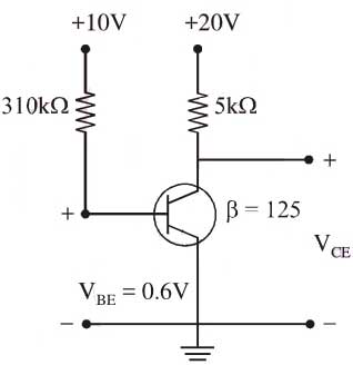
Ques 46. A transistor is operating in common emitter mode as shown in the figure given below. The voltage Vce is
10.05 V
1.5 V
1.05 V✔
0.5 V
Let the transistor be in active region then by applying Kirchoff’s law to the base-emitter loop,
10 – IB (310 × 103 ) – 0.6 = 0
IB = 30.3225 mA
Ic = βIB
= 125 × 30.3225 × 10–6 = 3.79 mA
Now VCE = 20 – IcRc
= 20 – 5 × 10³ (3.79 × 10⁻³ )
= 1.05V
Ques 47. By increasing the transmission voltage to double its original value the same power can be despatched keeping the line loss
Equal to its original value
Half the original value
Double the original value
One-fourth of the original value✔
The line losses are inversely proportional to the square of voltage and power factor.
PL ∝ 1/V2
Now voltage is doubled
V2 = 2V1
PL1/PL2 = (V2/V1)2
= (2V1/V1)2
PL2 = PL2/4
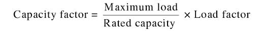
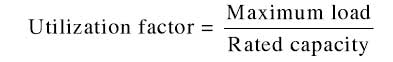
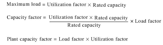
Ques 48. Which of the following is true?
Load factor = capacity factor x utilization factor
Utilisation factor = capacity factor x load factor
The capacity factor indicates the extent of the use of the generating station. It is different from the load factor because of the reason that the rated capacity of each plant is always greater than the expected maximum load due to some reserve capacity. Thus
Utilization Factor
It is defined as the ratio of maximum demand to the rated capacity of the plant
Ques 49. An electric load consumed 17.32 kW at a power factor of 0.707 (lagging). For changing the load power factor to 0.866 (lagging), the capacitor that is to be connected in parallel with the load should draw
7.32 kVAR✔
10 kVAR
27.32 kVAR
10.32 kVAR
Leading kVAr taken by the capacitor,
Q = P(tanΦ1 – tanΦ2)
CosΦ1 = 0.707
Φ1 = 45°
CosΦ2 = 0.866
Φ2 = 30°
Q = 17.32 (tan 45° – tan 30°)
= 7.32 KVAR
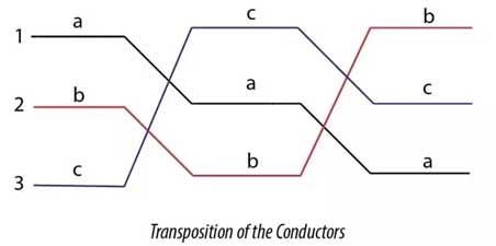
Ques 50. The most appropriate way of mitigating the problem of interference between the power line and the commutation line is to
Transpose the power line✔
Transpose the communication line
Use the double circuit power line
Use bundled conductor power line
Transposition of overhead line conductors refers to exchanging the positions of power conductors at regular intervals along the line so that each conductor occupies the original position of every other conductor over an equal distance in order to reduce crosstalk and otherwise improve transmission.
Usually, the telecommunication line and power lines travel close to each other, then the current flowing through the power line produces magnetic flux linkage between the telecommunication line so that voltage is induced in the telecommunication line which causes the disturbance in communication. This phenomenon is called radio interference which is suppressed by the transpose of the power line.
The transposition arrangement of the conductor can simply show in the following figure. The conductor in Position 1, Position 2, and Position 3 changes in a specific arrangement to reduce the effect of capacitance and the electrostatic unbalanced voltages.
For SSC JE 2017 Electrical paper with complete solutionClick Here
For SSC JE 2015 Electrical paper with complete solutionClick Here
For SSC JE 2014 (Evening shift) Electrical paper with complete solutionClick Here
For SSC JE 2014 (Morning shift) Electrical paper with complete solution Click Here
For SSC JE 2013 Electrical paper with complete solutionClick Here
For SSC JE 2012 Electrical paper with complete solutionClick Here