SSC JE 2011 Electrical question paper with Explained Solution | MES Electrical
Ques 1. If in an R-L-C series circuit the current lags the applied voltage by 60° then
XL – Xc = R/√3
XL – Xc = √3R✔
XL = Xc = R
XL – Xc = R
Since Angle between V and I is 60°
Then Power factor angle = θ = 60°
For series RLC Circuit the phase difference between the current and the voltage is
tanθ = (XL – Xc)/R ……. (Since XL > Xc)
tan60° = (XL – Xc)/R
√3R = (XL – Xc)
Ques2. A lossy capacitor with loss angle of 0.01 radian, draws a current of 0.5 A when supplied at 1000 V from a sinusoidal voltage source. The active power consumed by the capacitor is
5 W✔
10 W
2 W
1 W
Loss angle = 0.01 radian
θL = 0.01 x 180/π = 0.57 ———- (Converting radian into degree)
P.F. angle = 90 – 0.57 = 89.43
Active power consumed = V I cosθ
= 1000 × 0.5 × cos(89.427)
= 4.999 ≅ 5
Ques 3. An AC voltage source with an internal impedance Z 1 is connected to a load of impedance Z2. For maximum power transfer to the load, the condition is
Z2 = Z1
|Z2| =|Z1|
Z2* = Z1
Z2 = Z1*✔
For maximum power transfer, input Impedance must be equal to the conjugate of output Impedance.
As we know The impedance of input of something to which a signal is applied is a measure of how much power that input will tend to draw (from a given output voltage). This impedance is known as the load impedance.
Therefore Z2 = Z1*
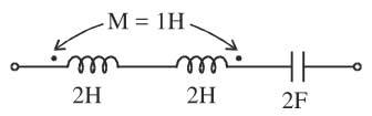
Ques 4. The resonant frequency of the AC series circuit shown in the figure given below, in Hz is
1/4π√3
1/4π√2
1/4π✔
1/4π√10
When the coils are joined in series with additive flux the equivalent inductance is
Leq = L1 + L2 – 2M = 2 + 2 – 2 x 1 = 2H
The resonant frequency of the AC series circuit in Herz is given as
F = 1/2π√LC
Where L = 2H & C = 2F
F = 1/2π√LC = 1/2π√4
= 1/4π
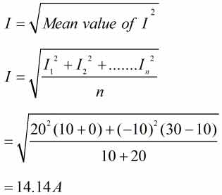
Ques 5. A current wave starts at zero, rises instantaneously, then remains at a value of 20 A for 10 sec, then decreases instantaneously, remaining at a value of – 10 A for 20 sec, and then repeats this cycle. The RMS value of the wave is
22.36A
17.32 A
8.165 A
14.14 A✔
RMS Value of the current of the sine wave is
Ques 6. Two incandescent bulbs of rating 230 V, 100 W and 230 V, 500 W are connected in parallel across the mains. As a result what will happen?
100 W bulb will glow brighter
500 W bulb will glow brighter✔
Both the bulbs will glow equally bright
Both the bulbs will glow dim
In a parallel connection, the voltage across each element is same. So when a 100W bulb and 500W bulb are connected in parallel, the voltage across them will be the same (230 V in the given case). To find which bulb will glow brighter we need to find the power dissipation across each of them. From the relation
P = V2/R
R100 = 2302/100 = 529 Ohm
R500 = 2302/500 = 105.8 Ohm
Since the voltage is the same we can say that power dissipation will be higher for the bulb with lower resistance i.e. 500W bulb.
Therefore 500-watt bulb will glow brighter.
Ques 7. In two wattmeter method of measurement of three-phase power of a balanced load, if both the wattmeters indicate the same reading, then the power factor of the load is
Zero
Unity✔
0.8 lagging
0.8 Leading
The power factor of the wattmeter is given as
Second method
Reading of Wattmeter 1 “W1”
W1 = VLIL Cos(30 + Φ)
Reading of Wattmeter 2 “W2”
W2 = VLIL Cos(30 – Φ)
When load P.F cosΦ = 1 then Φ = 0° so that
W1 = W2 = VLIL Cos30
Ques 8. Measurement of ________ is affected by the presence of thermo-emf in the measuring circuit
High resistance
Low Resistance✔
Capacitance
Inductance
In the galvanometer circuit, the dissimilar metals come in contact and generate the thermal e.m.f.s. Such thermal e.m.f.s may cause the en’0rs while measuring low-value resistances. To prevent this, more sensitive galvanometers having copper coils and copper suspension systems are used.
Ques 9. The response time of an indicating instrument is determined by its
Deflecting system
Damping system✔
Controlling system
Support type of Moving system
The major function of the damping system is to produce a damping force while the moving system is in motion. The damping force should be of such magnitude that the pointer of the moving system comes to its final steady value quickly without any oscillation.
The response time of an indicating instrument is determined by the Damping system.
If the moving system reaches its final position rapidly and smoothly without oscillations, the instrument is said to be critically damped.
If the moving system oscillates about the final stead, position with a decreasing amplitude, and take some time to come to rest then the instrument is said to be underdamped.
The instrument is said to be overdamped if the moving system moves slowly to its find steady position.
In practice, slightly underdamped systems are preferred.
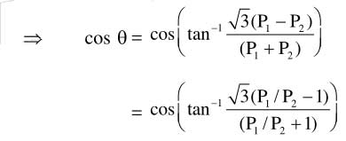
Ques 10. The ratio of the reading of two wattmeters connected to measure active power in a balanced 3-phase load is 2:1. The power factor of the load is