Ques 81. The direction of rotation of a DC shunt motor can be reversed by interchanging
The armature terminal only
Either field or armature terminals✔
The supply terminals
The field terminals only
The direction of rotation of a DC shunt motor can be reversed by interchanging leads of either the field winding or the Armature Winding.
Generally changing the direction of the field is easier, because it carries lesser current as compared to armature current. However, the reversal should not be done while the armature is excited.
Ques 82. AC series motors are built with as few turns as possible to reduce
Flux
Reactance✔
Iron losses
Speed
Why an AC series Motor are Built with few turns?
The AC series motor operates on either AC or DC circuits. When an ordinary DC series motor is connected to an AC supply, the current drawn by the motor is low due to the high series-field impedance. The result is low running torque. To reduce the field reactance to a minimum, AC series motors are built with as few turns as possible.
The decrease in the number of turns of the field winding reduces the load torque, i.e., if the field turns to decrease, its MMF decreases and then flux, which will increase the speed, and hence the torque will decrease. But in order to maintain constant load torque, it is necessary to increase the armature turns proportionately.
If the armature turns to increase, the inductive reactance of the armature would increase, which can be neutralized by providing the compensating winding.
Ques 83. Based on revolving field theory, the forward and backward frequencies of the rotor emf of a 4-pole, 50 Hz, single-phase induction motor when running at 1300 rpm in the same direction of the forward field are respectively
6.67 Hz, 93.33 Hz
107.69 Hz, 7.69 Hz
93.33 Hz, 6.67 Hz✔
7.69 Hz, 107.69 Hz
Forward field slip Speed
SF = (Ns -Nr)/Ns
Synchronous speed Ns = 120f/p = 120×50/4 = 1500
(1500 – 1300)/1500 = 0.133Hz
Rotor frequency due to forward field = SF x F = 0.133 x 50 = 6.67 Hz
Backward slip of an induction motor
Sb = (2 – Sf) = 2 – 0.133 = 1.87 Hz
Rotor frequency due to Backward field = Sbx F = 1.87 x 50 = 93.35Hz
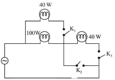
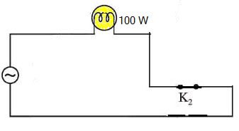
Ques 84. Three lamps are in the circuit as shown in the figure. At what condition 100 W lamp will have the maximum brightness?
Key K 1 is open, K 2 is closed and K 3 is open✔
K 1 is closed, K 2 is open and K 3 is also open
Both (1) and (2)
Key K 1 is closed, K 2 is open and K 3 is closed
If the Key 2 is closed while the Key 3 and Key 1 is open, the circuit is closed for 100 W lamp and the lamp will glow with maximum brightness
If key 1 is closed while the other 2 are open then 100W and 40 W lamps will glow and In a series connection, the current flowing across each element is the same. So when a 40W bulb and 100W bulb are connected in series, the same current will flow through them. Since both bulbs are rated at the same voltage, we can say that the resistance of each bulb is inversely proportional to its rated power. Hence 40 W bulb will glow brighter.
Ques 85. Given two coupled inductors L 1 and L 2 having their mutual inductance M. The relationship among them must satisfy
M > L1L2
M ≤ L1L2✔
M = L1L2
M > (L1 + L2)/2
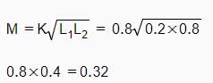
The expression for mutual inductance
M = K√L1L2
Now the value of the coefficient of coupling K lies between 0 and 1 i.e Mutual inductance is maximum when K = 1 and mutual inductance is zero when K = 0
So K ≤ 1
∴ M ≤ √L1L2
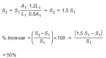
Ques 86. If the length of a bar of magnetic material is increased by 20% and the cross-sectional area is decreased by 20% then the reluctance is
Increased by 50%✔
Decreased by 33%
Increased by 67%
Remaining same
The reluctance of a uniform magnetic circuit can be calculated as:
S = L/μA
S2/S1 = A1 L2/A2 L1
Since length l2 of the bar is increased by 20% = 120/100 = 1.2 i.e
L2 = 1.2L1
And area is decreased by 20% = 80/100 = 0.8 i.e
A2 = 0.8A1
Ques 87. Two coupled inductors L1 = 0.2 H and L2 = 0.8 H, have a coefficient of coupling K = 0.8, The mutual inductance M is
0.16 H
0.02 H
0.32 H✔
0.24 H
The expression for mutual inductance
Ques 88. A coil with a certain number of turns has a specified time constant. If the number of turns is doubled, its time constant would
Become doubled
Get halved
Remain Unaffected
Become Fourfold✔
The self-inductance of a solenoid is given as
L = μN2A/I = L1
where
N is the number of turns of the solenoid
A is the area of each turn of the coil
l is the length of the solenoid
and μ is the permeability constant
so, if the number of turns was to be doubled the self-inductance would be
L2 = u (2N)2A/l
or
L2 = 4L1
it would be quadrupled or increased fourfold.
Ques 89. The iron loss per unit frequency in a ferromagnetic core, when plotted against frequency, is a
Constant
Straight-line with positive slope✔
Straight-line with a negative slope
Parabola
Both hysteresis loss and eddy current loss give rise to heat in a magnetic circuit. The two losses are usually taken together and are called ‘iron loss’.
Pi = PE + PH
Pi = f2B2max + f B1.6max
Iron losses thus vary with both frequency and magnetic flux density. The power transformer is likely to be fed at the constant frequency and at the constant voltage, which means that magnetic flux density is almost constant. Thus iron losses in a transformer are constant from no load to full load.
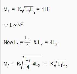
Ques 90. The mutual inductance between two closely coupled coils is 1 H. If the turns of one coil is decreased to half and those of the other is doubled, the new value of the mutual inductance would be