
Ques.11. Copper conductors are generally used for transmission lines because of it
- Is good for spans
- Require more insulator
- Has a long life and high conductivity✓
- Requires more support
An overhead transmission line has groups of conductors running parallel to each other, carried on line supports. An electric transmission line conductor has four parameters: which are the series combination of resistance, inductance, shunt combination of capacitance, and conductance. The material used as the conductor for power transmission and distribution lines must possess the following characteristics: Copper and aluminum conductors are used for overhead transmission of electrical power. In the case of high voltage transmission, aluminum with a steel core is generally used. Sometimes cadmium, copper phosphor, bronze, copper weld, and galvanized steel are also used as transmission conductors. The choir of the conductor used for transmission purely depends upon the cost, as well as required electrical and mechanical properties. Materials employed for transmission lines are Copper: Copper is an ideal material for overhead lines due to its high electrical conductivity and greater tensile strength. It is always used in the hard-drawn form as the stranded conductor. Although hard drawing decreases the electrical conductivity slightly, it increases the tensile strength reasonably. Copper has a high current density, that is, the current-carrying capacity of copper per unit of cross-sectional area is quite large. This leads to two advantages: 1. Smaller cross-sectional area of the conductor is required. 2. The area offered by the conductor to wind load is reduced. Moreover, this metal is quite homogeneous, durable, and has high scrap value. There is no doubt that copper is an ideal material for the transmission and distribution of electric power. However, due to its high cost and nonavailability, it is rarely used for these purposes. Nowadays the trend is to use aluminum in place of copper.
Ques.12. In motor circuit static frequency changers are used for __________
- Power factor improvement
- Speed regulation✓
- Improve cooling
- Reversal of direction
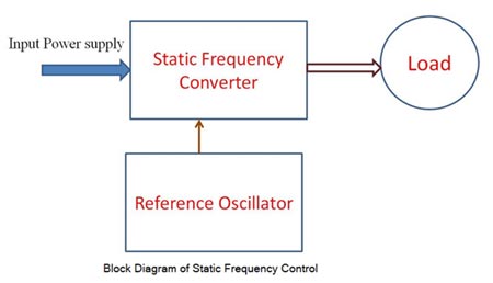
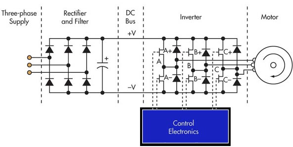
An ac motor can also be used as a drive motor. Among the motors used are induction motors and synchronous motors. Both slip ring and squirrel cage induction motors are used. Squirrel cage motor has advantages overslip ring one in that it is robust and has a simple construction. When compared to a dc motor it has a large power/weight ratio. An ac motor is normally a constant speed machine and its speed control over a wide range in a smooth and step-less manner had been a problem. It is well known that the speed of an ac motor can be varied if the supply frequency can be varied. The speed control can be smooth if a continuously variable frequency supply is available. Rotating machines have been used to provide a variable frequency supply. Similar to the conventional Ward-Leonard system for dc motor, an MG (Motor- Generator) set is used here to provide variable frequency supply. The system has the disadvantage of high initial cost, poor efficiency and it occupies plenty of space. But the advent of thyristors and thyristor power converters has paved the way for static frequency conversion. The ability to achieve a voltage or current of controllable frequency using thyristors presents the possibility of a variable speed drive using an ac motor. The static frequency conversion has several advantages over rotating frequency conversion equipment. The ac motor can have precise speed control. However, when the supply frequency is varied, the voltage applied to the motor should also be simultaneously varied to avoid saturation. Static frequency conversion equipment can be controlled to, provide a variable voltage supply, and the advantage is that they can be independently varied. The ac motor is operated at constant flux at every operating frequency. Static frequency converter is a device that alters the frequency of the input signal according to the input set point. As the name specifies, it consists of solid-state switching devices which are either on or off according to the input control signal. The following figure shows the essential elements of a static frequency converter. The 3-phase supply is rectified and filtered to produce a DC bus, which powers the inverter section of the static frequency converter. The inverter consists of three pairs of semiconductor switches (MOSFET, GTO, power transistor, IGBT, etc.) with associated diodes. Each pair of switches provides the power output for one phase of the motor. Each pair of semiconductor switches is driven by the control electronics to generate a high-frequency square wave carrier pulse waveform at each of the phase outputs. Since the carrier is identical on all three phases, the net voltage appearing across any phase of the motor windings due to the carrier alone is zero. In order to drive the motor, the control electronics generate three low-frequency sine waves, 120 degrees apart, which modulate the carrier pulses to each pair of switches. The width of the positive and negative pulse within each carrier cycle is modulated according to the amplitude of the low-frequency sine waveform of that phase. As a result, the average voltage presented to the motor winding is approximately sinusoidal. The two other phases of the motor winding have similar average voltages spaced 120 degrees apart. As static frequency converters operate with an output frequency from a few Hz up to about 100 Hz, they use a carrier frequency in the range of 2 kHz up to about 10 kHz. As power semiconductors improve, the trend is to increase carrier frequencies up to ultrasonic frequencies (> 18 kHz), which can lower losses in the motor since the current is more sinusoidal. The downside is higher switching losses in the inverter and potential for more radiated frequency noise. The are three basic types of Static converters as follows: The static frequency conversion is achieved using single-stage conversion devices like cyclo- converters or two-stage conversion devices like dc-link converters. Using a cyclo-converter, a very good quality low-speed drive can be obtained having inherent regeneration and reverse rotation possibilities. A dc link inverter uses two stages for frequency conversion. The ac is first rectified to dc which is inverted back to ac of desired frequency. The voltage control of the inverter is obtained externally by the control of the firing angle of the rectifier. Sometimes certain advantages are achieved by controlling the voltage in the inverter itself. In these cases, the inverters are voltage source inverters (VSI). The advantages of static frequency conversion devices are as follows:Static Frequency Converter
Types of static Frequency converters
Ques.13. Which of the following motors is most suitable for signaling devices and timers?
- D.C shunt Motor
- D.C series Motor
- Reluctance motor✓
- Compound Motor
It is a single-phase synchronous motor that does not require d.c. excitation to the rotor. Its operation is based upon the following principle: Whenever a piece of ferromagnetic material is located in a magnetic field, a force is exerted on the material, tending to align the material so that reluctance of the magnetic path that passes through the material is minimized. The stator consists of a single winding called the main winding. But single winding cannot produce a rotating magnetic field. So for the production of a rotating magnetic field, the must be at least two windings separated by a certain phase angle. Hence staler consists of an additional winding called auxiliary winding which consists of the capacitor in series with it. Thus there exists a phase difference between the currents carried by the two winding and corresponding fluxes. Such two fluxes react to produce the rotating magnetic field. The technique is called the split phase technique of the production of a rotating magnetic field. The speed of this field is the synchronous speed which is decided by the number of poles for which stator winding is wound. The rotor carries the short-circuited copper or aluminum bars and acts as squirrel cage rotor of an induction motor. If an iron piece is placed in a magnetic field, it aligns itself in a minimum reluctance position and gets locked magnetically. Similarly, in the reluctance motor, the rotor tries to align itself with the axis of the rotating magnetic field in a minimum reluctance position. But due to rotor inertia, it is not possible when the rotor is at standstill. So rotor starts rotating near synchronous speed as a squirrel cage induction motor. When the rotor speed is about synchronous, the stator magnetic field pulls the rotor into synchronism i.e. minimum reluctance position, and keeps it magnetically locked. Then the rotor continues to rotate with a speed equal to synchronous speed. Such a torque exerted on the rotor is called the reluctance torque. Thus finally the reluctance motor runs as a synchronous motor. The resistance of the rotor must be very small and the combined inertia of the rotor and the load should be small to run the motor as a synchronous motor. Advantages The reluctance motor has the following advantages Limitations The reluctance motor has the following limitation Applications This motor is used in signaling devices, control apparatus, automatic regulators, rerecording instruments, clocks and all kinds of timing devices, teleprinters, gramophones etc.Reluctance Motor
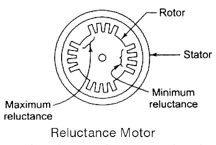
Working Principle of Reluctance Motor
Ques.14. Which of the following fuse is very fast in operation?
- KitKat fuse
- Semiconductor Fuse✓
- Cartridge fuse
- High rupturing capacity type
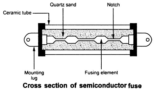
The semiconductor fuse is very fast-acting and is commonly referred to as an I2T fuse. Besides the voltage and current ratings of the fuse, the I2T rating plays an important role. For the proper protection of the SCR coordination of the SCR’s and fuse’s I2T ratings are critical. The I2T of the fuse must be smaller than the SCR’s in order to protect the SCR. The semiconductor fuse operates at a high temperature (over 100°C) in order to make it fast-acting. As with all fuses, the steady-state operation of the fuse should be at approximately 80% of its current rating. Fig. shows the internal structure of the semiconductor fuse. The fusing element is made of silver with one or more notches. The cross-section of the fuse at the notch is less. When heavy current flows through the fuse, there is a high current density at the notch. Because of high current density, the temperature rises at the notch, and the arc is developed. This arc reduces the current flow. Therefore high voltage is formed across the notch. This further increases the temperature. Therefore the fuse element is vaporized and arc length is increased. Due to increased arc length, the current further reduces. At some stage, the current is zero and the fuse becomes open. There is no arc and the complete voltage appears across the fuse. Note that the fuse has to withstand the voltage in open conditions. The fusing element is embedded in quartz sand. This helps to conduct heat and serves as a quenching medium for the arc at the time of fusing. Note:- KitKat fuse is a low voltage fuse. A cartridge fuse is a high voltage fuse.Semiconductor Fuse
Ques.15. The dead time of an instrument refers to
- The large change of input quantity for which there is no output.
- The time encountered when the instrument has to wait for some reactions to take place
- Retardation or delay in the response of an instrument to a change in the input signal✓
- The dead time of an instrument is equal to zero.
Dead time:- A time during which a new signal or variation in a signal cannot be detected due to some physical characteristic of the system or the transducers is known as dead time. In any control system with feedback, the system cannot respond instantly to any change and thus there are delays while the system takes time to accommodate the change. Such delays are referred to as dead time or Ings. For example, in the control of the temperature in a room by means of a central heating system, if a window is suddenly opened and the temperature drops or the thermostat is suddenly set to a new value, a lag will occur before the control system responds, switches on the heater and gets the temperature back to its set value.
Ques.16. For a 100% efficient transformer, the primary winding has 1000 turns and the secondary 100 turns. If the power input to the above transformer is 1000 watts, the power output is
- 100 Watts
- 10 Watts
- 1 Watt
- 1000 Watts✓
If a transformer is 100% efficient then Power supply to the primary = Power supply to the secondary. Power supply to primary = 1000 Watt (given) Therefore the power supply to the secondary = 1000 watt
Ques.17. In the given network, the ideal closed-loop voltage gain is ______
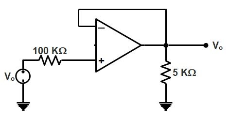
- ∞
- −1
- 1✓
- 0
Given the circuit is the non-inverting amplifier. The closed loop gain of the non-inverting amplifier (AV ) = 1+ RF /R2 RF = 0 ( feedback resistor) AV = 1+0/5 = 1V
Ques.18. The relative permeability of paramagnetic material is __________
- Less than unity
- Greater than unity✓
- Equal to unity
- Infinity
Permeability is a measure of how easy it is to establish the flux in a material. Ferromagnetic materials have high permeability and hence low Reluctance, while nonmagnetic materials have low permeability and high Reluctance. Relative permeability is the ratio of magnetic permeability of the medium (µ) to the magnetic permeability of free space (µo) is defined as relative permeability (µr), i.e. µr = µ/µo The substances, which when placed in an external magnetizing field, get magnetized feebly in the direction of the magnetizing field are called paramagnetic. Examples of paramagnetic substances are Aluminium, antimony, platinum, manganese, sodium, chromium, copper chloride, liquid oxygen etc. Paramagnetic materials possess a relative permeability µr that is slightly larger than 1. One example of this type of material is aluminum, for which cur= 1.00000036. Therefore, as with the diamagnetic materials, we can consider the materials as having µr = 1 for most practical purposes. In general, the effect due to paramagnetism is negligible.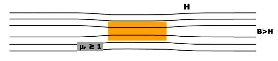
Ques.19. In an R-L-C series circuit, during resonance, the impedance will be _____.
- Maximum
- Zero
- Minimum✓
- Negative
In RLC series circuit the total impedance of the series LCR circuit is given as Z2 = R2 + (X1 – X2)2 where X1 is inductive reactance and X2 is capacitive reactance. At a particular frequency (resonant frequency), we find that X1=X2 because the resonance of a series RLC circuit occurs when the inductive and capacitive reactances are equal in magnitude but cancel each other because they are 180 degrees apart in phase. Therefore, the phase angle between voltage and current is zero and the power factor is unity. Thus, at the resonant frequency, the net reactance is zero because of X1=X2. The circuit impedance Z becomes minimum and is equal to the resistance R. “Since the impedance is minimum, the current will be maximum”. Hence electrical resonance is said to take place in a series LCR circuit when the circuit allows maximum current for a given frequency of alternating supply at which capacitive reactance becomes equal to the inductive reactance.
Ques.20. For making capacitors, it is better to select a dielectric having _________
- Low permittivity
- High permittivity✓
- Permittivity equal to the air
- Zero permittivity
Dielectric constant refers to the material situated between the capacitor’s plates. No capacitor can maintain a charge on its plates unless the material or mixture of materials between them has some tendency to insulate. The dielectric constant εr represents the degree to which a substance or common mixture of substances tends to reduce the electric field between the plates. Hence, the capacitance is directly proportional to the dielectric constant, and the true quantitative definition of capacitance is: C = εrε0 A/d C is the capacitance, in farads; A is the area of overlap of the two plates, in square meters; εr is the relative static permittivity (sometimes called the dielectric constant) of the material between the plates (for a vacuum, εr = 1); ε0 is the electric constant, vacuum permittivity, permittivity of free space (ε0 ≈ 8.854×10⁻¹² F⋅m−1) d is the separation between the plates, in meters; From the above equation, the capacitance of the capacitor is directly proportional to the permittivity. If permittivity is high then the capacitance of the capacitor will be also high. Note:- When two conducting plates are brought closer and are separated by another plate that is made up of insulating material leads to the formation of the capacitor. The insulating material used in it is balled dielectric material. The main function of dielectric material is to store electrical energy. Thus dielectric materials are used in capacitors. There are four types of capacitors available depending on the dielectric material used in them. 1. Capacitors with air and gases as dielectric:- Such capacitors are used in circuits where energy loss in them should be low as well as the value of capacitance should be small. Thus, these types of capacitors are used in circuits where accuracy is the prime concern, for example, radiofrequency circuits. 2. Capacitors with mineral oil as dielectric:- These capacitors give a large value of capacitance with a small amount of dielectric loss. 3. Capacitors with a combination of solid and liquid as dielectric paper, glass, mica, mineral oil, caster oil, etc. are used in these types of capacitors. Oil impregnated paper dielectric is used for making capacitors that should have a large value of capacitances. These types of capacitors are used in power distribution systems. 4. Capacitors with only solid as dielectric such as glass, mica, etc. These capacitors are used in laboratories. Mica has a high dielectric constant, high dielectric strength, and low dielectric loss. Further, the dielectric constant of mica does not change much with temperature. Most of the capacitors are constructed as sealed components.