
Ques.21. The conductors used for transmitting power must have the given characteristics.
- Low cost and high tensile
- Lightweight
- The low value of specific resistance
- All of the above✓
An overhead transmission line has groups of conductors running parallel to each other, carried on line supports. An electric transmission line conductor has four parameters: which are the series combination of resistance, inductance, shunt combination of capacitance and conductance. The material used as the conductor for power transmission and distribution lines must possess the following characteristics: Copper and aluminum conductors are used for overhead transmission of electrical power. In case of high voltage transmission, aluminum with a steel core is generally used. Sometimes cadmium, copper phosphor, bronze, copper weld, and galvanized steel are also used as transmission conductors. The choice of the conductor used for transmission purely depends upon the cost, as well as required electrical and mechanical properties.
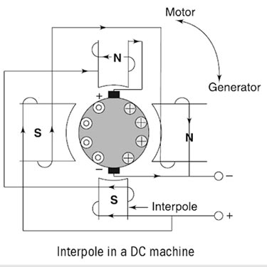
Ques.22. In a D.C. machine, how are the commutating pole winding connected?
- In series with the armature winding✓
- In parallel with the armature winding
- In series with the shunt winding
- In parallel with the armature winding
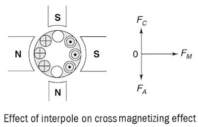
Thus, we can conclude that: The MMF induced on the interpoles must be sufficient enough to neutralize the effect of armature reaction and to produce enough field in the interpole winding to overcome the reactance voltage due to commutation. Another important function of the interpole is to neutralize the cross-magnetizing effect of the armature reaction, as shown in Fig. Here, vector FM represents the MMF due to main poles, FA represents the cross-magnetizing mmf due to the armature reaction and FC represents the interpole mmf which is directly opposite to the FA so that they cancel each other out. It is important to note here that the interpoles do not affect the flux distribution under the pole faces. So, even by using the interpoles in the machine, the flux weakening problem is not completely eliminated. Most medium-sized general-purpose motors correct the sparking problems with the interpoles and just live with the flux weakening problems. Main Functions of the InterpoleInterpoles winding or Commutating Pole Winding In DC Machine
Ques.23. NEMA standards rate motors according to ________
- Weight
- Horsepower
- Voltage
- Frame✓
Ques.24. What is the maximum length of the flexible conduit in the motor installation?
- More than 5 meter
- Less than 1.25 meter✓
- Less than 2.25 meter
- Less than 3.25 meter
An electrical conduit is a tube used to protect and route electrical wiring in a building or structure. The electrical conduit may be made of metal, plastic, fiber, or fired clay. Most conduit is rigid, but flexible conduit is used for some purposes. A motor connection is the means by which the power leads are terminated to a motor. From the estimator’s perspective, the motor terminations must also account for connecting the flexible conduit and fittings from the rigid conduit to the motor terminal box at its use point. Flexible conduit to motors serves four functions. According to the National electric code (NEC), the NEC does restrict the length of the flexible metal conduit of the motor leads between the motor and required junction box to a maximum of 6 ft(1.8 m) to limit the ground return path.
Ques.25. Strain gauge rosettes are used when _________
- The direction of hoop stress is not known
- The direction of principal stress is known
- The direction of principal stress is not known✓
- The direction of longitudinal stress is not known
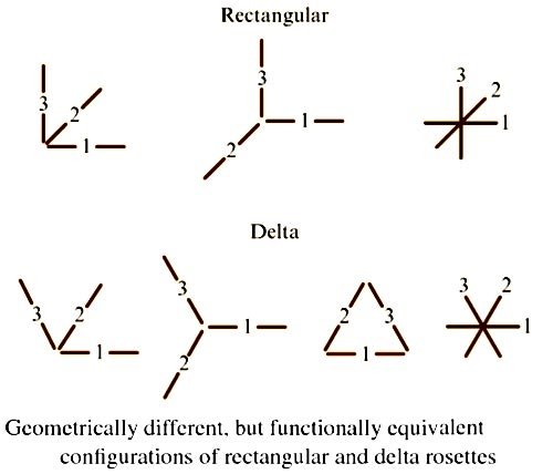
A strain-gauge rosette is, by definition, an arrangement of two or more closely positioned gage grids, separately oriented so as to measure the strains along with different directions in the underlying surface of a test part. Rosettes are designed to serve a very practical purpose in experimental stress analysis. It can be shown that for the not uncommon case of the general biaxial stress state, with the principal directions unknown, three independent strain measurements (in different directions) are required to determine the principal strains and stresses. Even when the principal directions are known in advance, two independent strain measurements are needed to obtain principal strains and stresses. For the purpose of meeting these requirements, strain-gage manufacturers typically offer three basic types of strain gage rosettes, each in a variety of forms: As illustrated in Fig. rectangular and delta rosettes may appear in any of several geometrical different, but functionally equivalent, forms. When the directions of the principal strains are unknown, a three-element rectangular or delta rosette is required, and the rosette can be installed without regard to orientation. Functionally, there is little difference between the rectangular and delta rosettes. Because the gage axes in the delta rosette have the maximum possible uniform angular separation (effectively 120°), this rosette is assumed to yield the optimum sampling of the underlying strain distribution.Strain-Gauge Rosettes
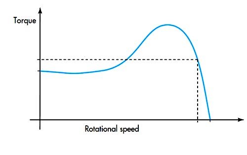
Ques.26. Which of the following motors is represented by the characteristics curve shown below?
- D.C shunt Motor
- D.C Compound Motor
- D.C series Motor
- Asynchronous Motor✓
The induction motor is also known as an asynchronous motor. To start the induction motor, let us assume that the induction motor has been started without any load on it. The motor will come to its no-load speed, which may be at a slip as low as 0.1 percent. At full load, the motor runs at a speed of N. When mechanical load increases, motor speed decreases till the motor torque again becomes equal to the load torque. As long as the two torques are in balance, the motor will run at constant (but lower) speed. The motor may be loaded continuously till pull out (or break down) torque is developed, at which point the motor will Stop if more load is placed on it. 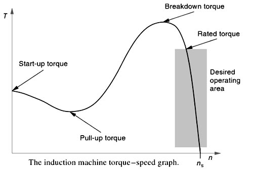
Ques.27. A current mirror can be used as an active load because______
- It has High A.C resistance
- It has Low A.C resistance
- Both High and low Resistance✓
- It has low D.C resistance
A current mirror is a circuit designed to copy a current through one active device by controlling the current in another active device of a circuit, keeping the output current constant regardless of loading. Basically, a current mirror is a circuit that receives a current at the input and provides a copy of it at the output. This function can be theoretically modeled by a dependent current source, as mentioned before. Current mirrors are used to copy both DC and AC currents. In the applications where a current mirror is mainly employed to take part in the AC function of a circuit, its input and output resistances become important. Because the input and output signals are currents, an ideal current mirror is expected to have zero input resistance which helps to keep the input current constant regardless of drive conditions, and infinite output resistance which helps to keep the output current constant regardless of load conditions.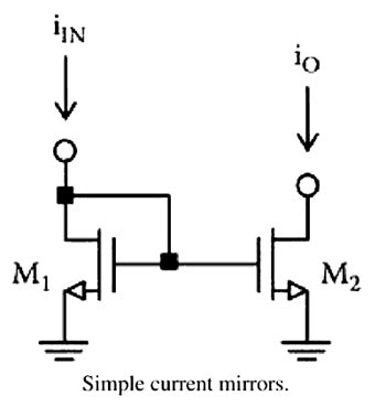
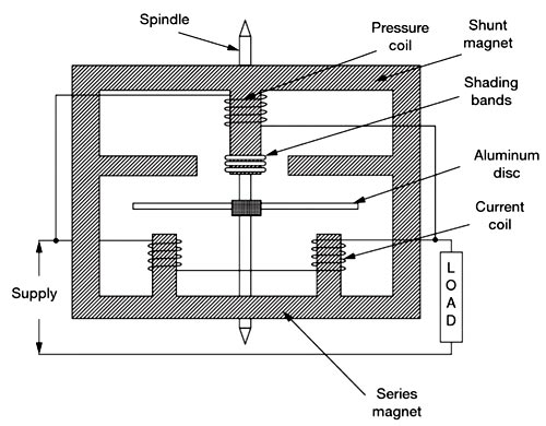
Ques.28. The series magnet of a single-phase Energy meter consists of the coil of _____.
- Thin wire of few turns
- Thin wire of more turns
- Thick wire of few turns✓
- Thick wire of more turns
An induction-type instrument can be used as an ammeter, voltmeter, or wattmeter, the induction-type energy meters are more popular. Induction-type single-phase energy meter is used invariably to measure the energy consumed in an AC circuit in a prescribed period where supply voltage and frequency are constant. The energy meter is an integrating instrument that measures the total quantity of electrical energy supplied to the circuit in a given period. A single-phase energy meter has four essential parts: Operating System The operating system consists of two electromagnets. The cores of these electromagnets are made of silicon steel laminations. The coils of one of these electromagnets (series magnet) are connected in series with the load and are called the current coil. The Current coil consists of a few turns of thick wire, connected in series with the load. It carries full load current which depends upon the angle of lag or lead of the load. Therefore the currents in the pressure coil and current coil have a phase difference of nearly 90 degrees. The other electromagnet (shunt magnet) is wound with a coil that is connected across the supply, called the pressure coil. The voltage coil consists of many turns of fine wire encased in plastic, connected in parallel with the load, and is highly inductive. This coil is connected in parallel with the supply or load and carries current proportional to voltage. The current in this coil lags behind the voltage approximately 90 degrees. The pressure coil, thus, carries a current that is proportional to supply voltage. Shading bands made of copper are provided on the central limb of the shunt magnet. Shading bands as will be described later, are used to bring the flux produced by a shunt magnet exactly in quadrature with the applied voltage. The two field fluxes produced by the pressure coil and current coil act on the aluminum disc, induce eddy currents in the disc, and hence the disc rotates due to the interaction of the two fluxes developed. The speed of the disc is proportional to the product of voltage, current, and the number of revolutions of the disc (i.e. time). In other words, the disc speed is proportional to the energy consumed by the load. The number of revolutions completed by the disc for one kilowatts hour is called meter constant.Induction-type Single-phase Energy Meter
Ques.29. The angle of a series R-L-C circuit is leading if
- XL = 0
- XC = 0
- XL > XC
- XC > XL✓
When the load is inductive in nature the voltage leads the current by an angle φ. When the load is capacitive in nature the current leads the voltage by an angle φ. If the inductive reactance is greater than the capacitive reactance, i.e XL > XC the net reactance is inductive, then the RLC circuit has a lagging phase angle and if the capacitive reactance is greater than the inductive reactance, i.e XC > XL the net reactance is capacitive then the RLC circuit have leading phase angle and if both inductive and capacitive are the same, i.e XL = XC then the circuit will behave as the purely resistive circuit.
Ques.30. If three 30 μF capacitors are connected in series, the net capacitance is
- 90 μF
- 30 μF
- 10 μF✓
- 0 μF
When the capacitor is connected in series then the total capacitance 1/C = 1/C1 + 1/C2 + 1/C3 1/C = 1/30 + 1/30 + 1/30 C = 10μF