
Ques.31. Transmitting power at high voltage requires more ________
-
- Faster controls for minimizing the arcing of contacts
- Maintenance and protection of the equipment
- Lesser controls for minimizing the arcing of contacts
- Both 1 & 2✓
Suppose that power is to be transmitted from a power station to a home or a factory. Since power is the product of current and voltage (P = V x I), a given amount of power can be transmitted either at high voltage and low current or at low voltage and high current. The cables that transmit the power have resistance, and therefore some of the power is bound to be wasted by producing heat in the cables as the current flows through them. If the resistance of the cables is R. the heat energy produced in time t when a current I is flowing through them is I2Rt. Thus the amount of energy that is wasted is proportional to the square of the current in the cables. The most efficient way to transmit power is therefore at high voltage and low current. This is known as high tension transmission. When resistance is low, energy losses are low also. So that faster control for minimizing the arcing of contacts & maintained by a high level of the protective scheme. The second advantage of high voltage/low current transmission of electrical power is that low currents require thinner and therefore cheaper cables. A disadvantage is the high cost of the substantial insulation needed when employing high voltages. Let’s say R = 10 ohms If you try to send 100W over at 100V, you need to use 1A. Then the power lost in the cable is I2 x R = 12 x 10 = 10W. If you try to send the same 100W over at 1000V, you need to use 0.1A. Then the power lost in the cable is 0.12 x 10 = 0.1WWhy is electrical energy transmitted at high voltage and low current?
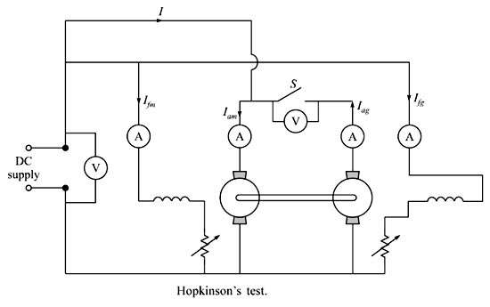
Ques.32. Two D.C. machines 500 kW each are tested by Hopkinson testing method. The power input would be
- 100 kW✓
- 1000 kW
- 500 kW
- None of the above
Hopkinson’s test is also referred to as the regenerative or Back-to-Back test. In Hopkinson’s test, we require two identical dc machines. This is a regenerative test. Both the dc machines are mechanically and electrically coupled and are tested simultaneously. One of the machines will act as a dc motor and the other as DC generator. The motor will rotate the generator and the generator will supply power to the motor. Now the question arises, if both machines help each other, then which one will supply the losses. The answer is external dc supply, which means, the input of the external supply will provide the power losses of both the machines. Now the voltage across switch S should be zero and only then we can declare that similar polarities of the machines are connected. So, when the switch S is closed both the dc machines are in perfect parallel connection and there is no chance of the presence of circulating currents between the two machines. Since in the case of the generator, the induced emf minus the armature drop is the terminal voltage and in case of the motor the induced emf plus the armature drop is the terminal voltage, the excitation of the generator will be more than the excitation of the motor to maintain the terminal voltages equal to one another. Obviously, the no-load iron loss and stray loss will not be equal for both the machines even though the machines are identical in all respects. Stray load loss is a very important factor in determining the efficiency of a dc machine. If we ignore this, we cannot determine the actual efficiency of the dc machine properly due to the following reasons. Stray load loss is the additional copper loss that occurs in the conductors on account of the non-uniform distribution of alternating currents. This increases the effective resistance of conductors and that is nothing but the skin effect. When the conductors carry load current, the teeth of the core get saturated and as a result, more flux passes down the slots through the copper conductors and thus setting up the eddy current losses in them. Due to the flux distortion, the net increase in the core loss occurs and the extra core loss is nothing but the core stray load loss. Thus the total power drawn from the supply is only for supplying internal losses of the two machines. Thus even very large machines may be tested as the power required is very small. Hence the power input in the given question will be 100 Watt. Advantages The various advantages of Hopkinson’s test are, Disadvantages:- The various disadvantages of Hopldnson’s test are,Hopkinson’s Test
Ques.33. Starting winding of a single-phase motor of a refrigerator is disconnected from the circuit by means of a
- Magnetic Relay✓
- Thermal Relay
- Centrifugal Switch
- None of these
The function of starting relay provided in the refrigerator is to start the split-phase induction motor by connecting the auxiliary winding or starting winding across the main supply in addition to the main winding at the time of starting. This helps to make the split-phase inflection motor as the self-induction motor is unable to start. The first method of disconnecting the starting winding of a split-phase motor can be done by using a centrifugal switch. Another method of disconnecting the auxiliary winding when the motor has picked up speed is by using an electromagnetic relay as has been shown in Fig The torque required to start the motor is significantly more than needed in the running condition At the starting time of the motor, electrical power is given to start the relay and winding of the motor. It also provides current to the starting winding of the motor. The starting winding provides sufficient torque so that the motor starts running. As the motor speed increases, the torque requirement decreases, and thereby current required by the motor also decreases. The current in starting relay is not able to hold the relay and it gets released which opens the starting winding contacts. Therefore, the starting winding gets disconnected.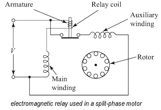
Ques.34. Two heaters, rated at 1000 W, 250 V each are connected in series across a 250 V, 50 Hz ac mains. The total power drawn from the supply would be __________ watt.
- 500✓
- 1000
- 250
- 750
Given Power P = 1000 Watts Voltage V = 250 Watts Since power and voltage are same therefore heater resistance R1 = R2 = V2/P = 2502/1000 = 62.5Ω Since two resistance are connected in series their equivalent resistance R = R1 + R2 = 62.5 + 62.5 = 125Ω Now total power drawn is P = V2/R = 2502/125 = 500 watt
Ques.35. The voltmeter is a galvanometer with
- Low resistance
- Zero Resistance
- High Resistance✓
- None of the above
The voltmeter is used to measure the potential difference (in volts) between two points. It is a moving coil galvanometer having a high resistance connected in series with its coil. By doing so the resistance of the voltmeter becomes very high. Hence, it takes very small current from the circuit when is connected across the circuit to measure the potential difference. Thus the potential difference t be measured by it does not fall. An ideal voltmeter should have infinite resistance. Let R be the resistance connected in series with the galvanometer, V the potential difference to be measured by the voltmeter. G is the resistance of the galvanometer and I is current through the galvanometer for full deflection Ig = V/(R + G)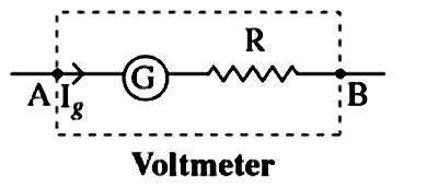
Ques.36. A three-phase induction motor is analogous to
- Generator
- Rotating transformer✓
- Rotating Motor
- Rotating converter
Answer. 2. Rotating Transformer Explanation:- Analysis of the transformer model is very easy to visualize than induction motor so, the induction motor is generalized as a transformer because of the following reasons : Because of the above reasons Induction motor is called a two windings transformer with secondary short-circuited.
Ques.37. In which of the following, it is not desired to attain the condition of maximum power transfer?
- Electronic circuit
- Communicational circuit
- Power system✓
- Computer circuit
Electronic Circuit:-In electronic circuits, it is often desirable to transfer maximum power e.g (i) The signal power available at the receiving antenna is very small. It is very important to recover the maximum possible amount of signal power from the receiving antenna. (ii.) In the public address system, it is desired that maximum power is transferred from the amplifier to the speaker (i.e load) in order to operate the speaker. To meet such situations in electronic circuits, we adjust the circuit for maximum power transfer. The technique is to make the load resistance (eg speaker) equal to the source (e.g amplifier) resistance. l he circuit is then said to be matched Power system:- Under the conditions of maximum power transfer, the efficiency is low (50%) and there is a greater voltage drop in the lines. In a power system, the goal is higher efficiency rather than maximum power. For these reasons, maximum power transfer is not desired in a power system.
Ques.38. The relative permeability of a material is 0.95. The material is
- Diamagnetic✓
- Paramagnetic
- Ferromagnetic
- Ferrimagnetic
Permeability is a measure of how easy it is to establish the flux in a material. Ferromagnetic materials have high permeability and hence low Reluctance, while nonmagnetic materials have low permeability and high Reluctance. Diamagnetic materials are materials with relative permeabilities slightly smaller than 1 (μr < 1). This class includes important materials such as mercury, gold, silver, copper, lead, silicon, and water. The relative permeability of most diamagnetic materials varies between 0.9999 and 0.99999 (susceptibility varies between (-10-5 and -10–4), and for most applications, they may be assumed to be nonmagnetic. An interesting aspect of diamagnetism is the fact that the magnetic flux density inside the diamagnetic material is lower than the external magnetic field. If we place a piece of diamagnetic material over a permanent magnet, the magnet will repel the diamagnetic material, as shown in Figure. 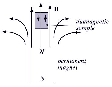
Ques.39. In a R-L series circuit the power factor P.F. is _________
- Leading
- Unity
- Zero
- Lagging✓
The RL series circuit is inductive in nature. The circuit consists of only inductance and resistance but not capacitance hence the power factor is lagging and the current lags the voltage by an angle φ.
Ques.40. A wire bent into a semi-circle in the center and straight at both ends is placed in a uniform magnetic field B pointing out of the page shown in the figure. If the wire carries the current I, the force on each straight section xy and zw is
- IB(Current × Magnetic field)
- IB(Length × Magnetic field)
- BIL✓
- Zero
If a current is placed in a region of the magnetic field, it will experience a magnetic force. In Figure, a magnetic field is established out of the page and a wire carries a current from left to right, perpendicular to the magnetic field. The magnitude of the force is proportional to the current I, the magnetic field magnitude B, and the length L of the wire that is in the magnetic field. Mathematically F ∝ BIL F =kBIL where k is a constant of proportionality. This constant can be made to equal one by proper choice of the unit of the magnetic field. We can make k = 1 by saying that when the force on 1 m of wire carrying a current of 1 A is 1 N. then the magnitude of the magnetic field is defined to be 1 Tesla (so 1 T = 1 N A−1 m−1). So the force on the current-carrying wire is F =BIL Remember, though, that the magnetic field we at right angles to the wire. If there is an angle between them then: The force on a length L of the wire is given by F = BIL sinθ where θ is the angle between the current and the direction of the magnetic field.The magnetic force on a current
