
Ques.41. The transmission lines which feed different sub-stations represent
- Primary transmission
- Secondary Transmission✓
- Primary distribution
- Secondary distribution
Electric power transmission, a process for the delivery of electricity to consumers, is the bulk transfer of electrical power. All major generating stations are usually interconnected by transmission lines or network that distributes the power from generating stations to the distribution systems, which ultimately supply the load points or load centers. Primary transmission: The generated electric power (in 132, 220, 500 kV, or greater) is transmitted to load points by the three-phase three-wire overhead transmission system. This type of transmission is called primary transmission, which is also known as extra-high-voltage AC (EHV-AC) transmission. Primary transmission is generally done through overhead transmission lines. The high voltage overhead lines are generally constructed by the aluminum alloy made up of several strands and reinforced with steel strands. The primary transmission uses a three-phase three-wire system. Secondary transmission: The primary transmission ends at a substation known as Receiving Station (RS), which is far from the city (outskirts). At receiving station, the level of voltage is reduced by step-down transformers up to 132, 66, or 33 kV, and electric power is transmitted by the three-phase three-wire overhead system to different substations located in the city. It is known as secondary transmission. The power is transmitted to various stations using the overhead 3-phase 3 -wire System. The conductor, used for the secondary transmission are called feeders. Distribution System:- At the substations, transformers are again used to step the voltage down to a lower voltage for distribution to commercial and residential users. This distribution is accomplished with a combination of sub-transmission (33 kV to 115 kV, varying by country and customer requirements) and distribution (3.3 to 25 kV). Finally, at the point of use, the energy is transformed to low voltage with the help of step-down transformers (100 to 600 V, varying by country and customer requirements). Similar to the transmission, the distribution of electric power is also divided broadly into two parts: (i) Primary Distribution: At the substations, the voltage level is reduced to 6.6 kV, 3.3 kV, and 1.1 kV with the help of a step-down transformer. It uses the 3-phase 3-wire underground system. And the power is further transmitted to the local distribution centers. This primary distribution is also called High Voltage (HV) Distribution. For the larger consumer-like factories and industries, the power is directly transmitted to such loads from a substation. Such big loads have their own substations. (ii) Secondary Distribution: At local distribution centers, the voltage level of 6.6 kV, 1.1 kV is further reduced to 440 V using distribution transformers. The power is then transmitted to the user or consumers; this is called a secondary distribution. The 1-phase lightning loads are supplied using a line and neutral wire. Loads like three-phase motors are supplied using the three-phase line
Ques.42. The number of conductors of the compensating winding in a D.C. machine
- Is always less than the number of armature conductors per pole✓
- Is always more than the number of armature conductors per pole
- Maybe less or more than the number of armature conductors per pole
- None of these
The purpose of compensating windings in DC machines is to compensate for harmful flux components created by armature windings. Flux components are harmful because they create an unfavorable air-gap flux distribution in DC machines. Compensating winding is connected in series with the armature winding in such a way that the current flowing in them is directly opposite to the current flowing in the armature located just below the pole faces. The MMF produced by the compensating winding is equal and opposite to the MMF produced by the armature at every point under the pole faces. Hence, the net MMF is just equal to the MMF produced by the main poles alone. As a result, the flux in the machine remains unchanged regardless of the load on the machine. Let the number of armature conductor = Z/P Number of armature conductors per pole = Z/2P Number of armature turns at any instant under one pole= Pole arc/Pole Pitch × Z/2P No. of armature amp-turns/pole for compensating winding = 0.7 × Z/2P Hence from the above equation, it is clear that the number of conductors of the compensating winding in a D.C. machine is always less than the number of armature conductors per pole.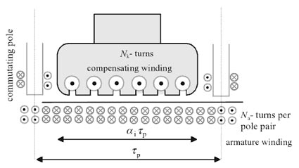
Ques.43. Steel rail poles of height 13 meters are used for transmission purpose of _____ voltage.
- 22 kV
- 11 kV
- 33 kV✓
- Any of the above
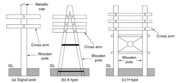
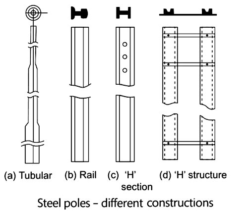
LINE SUPPORTS The main function of the line support is to support the conductors to keep them at suitable heights from the ground. Hence, in overhead lines, various types of supporting structures are used such as poles and towers which are called as line supports. Generally, line supports have the following properties: (i) Good mechanical strength (ii) Lightweight (iii) Cheap (iv) Longer life Various types of line supports are used in overhead transmission and distribution systems. The selection of line support depends on many factors such as cost, the span of the line, line voltage, local conditions, etc. The various types of line supports are as follows: This is one of the simplest forms of the line support. Generally, wooden poles are used. They are cheap, easily available, and have good insulating properties. These poles must be straight, strong, and free from knots. The poles should be properly seasoned to prevent rapid decay because of crakes. An aluminum, zinc, or cement cap is used at the top of the wooden pole to prevent decay due to snow and rain. They are widely used for distribution purposes up to 22 kV and short spans (up to 60 metros). In cities where timber is easily available and the cost of transportation of steel tower is more, single and double pole structures either A or H type are widely used for overhead lines for 130 kV and for the span of 150 meters as shown in Fig. Wooden poles generally rot below the ground level and to prevent this preservative compounds such as creosote oil is used. Advantages of Wooden Poles Disadvantages of Wooden Poles The drawbacks of wooden poles are absent in the steel poles and hence they are generally used as a substitute to the wooden poles. They have better mechanical strength and longer life. They can be used for a long span. These poles are used for distribution purposes in urban areas. These types of poles are generally galvanized or painted to increase their life. These poles are shown in Fig. Generally, three types of steel poles are available as follows: The tubular poles are generally 9-11 m long and at invariably used for LV distribution in cities and other urban areas. The steel rail poles of 11-13 m height are freely used for power lines of 11, 22 and 33 kV. The H-type structures using rails and rolled sections are often used to support the ‘micro’ substation (comprising HV load-break switch, transformer upto 100 kVA and LV distribution panel) are very commonly employed in rural and suburban (i.e., except in big cities) primary and secondary distributions. Advantages of Steel Poles Disadvantages of Steel PolesWooden Poles:
Steel Poles
Ques.44. A freshly painted layer may be dried electronically by_______.
- Emissive Heating
- Induction Heating
- Infrared heating✓
- Convection heating
Infrared heating:- Infrared heating is generated by i^2R losses in heating lamps or devices, and this is a special case of resistance heating. The difference, however, is that infrared energy can be generated in a narrow bandwidth. This can be applied more efficiently in some cases than combustion energy that spans a broader bandwidth. To be most efficient, infrared heaters should concentrate their output at the peak of the absorption spectrum for the material being heated. It can transfers energy to a body with a lower temperature through electromagnetic radiation. Depending on the temperature of the emitting body, the wavelength of the peak of the infrared radiation ranges from 780 nm to 1 mm. No contact or medium between the two bodies is needed for the energy transfer. Infrared heaters can be operated in a vacuum or atmosphere. There are applications in papermaking, drying paints and enamels, and the production of chemicals and drugs.
Ques.45. Dynamometer type moving coil instruments are provided with _____
- Pneumatic damping
- Eddy current damping
- Fluid Damping
- Air fiction damping✓
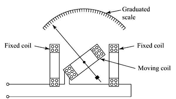
In dynamometer-type instruments, there is one fixed coil and one moving coil. The fixed coil is, however, made in two sections, and placed apart as shown in Fig. The moving coil is free to move on a spindle. The pointer is attached to it and will move over a graduated scale when the moving coil gets deflected. This instrument can be used as an ammeter, voltmeter, and wattmeter for the measurement of current, voltage, and power, respectively. For use as an ammeter and voltmeter, both the fixed coils and the moving coil are connected in series. For use as a wattmeter, the fixed coils will carry the line current while the moving coil will carry a current proportional to the voltage. That is, in a wattmeter, the fixed coils, which are also called the current coils, are connected in series with the load whose power is being measured and the moving coil, which is also called the voltage coil or pressure coil, is connected across the supply voltage. As wattmeter, the deflecting torque will be proportional to the power in an ac circuit, i.e P = VI cosφ where cosφ is the power factor of the circuit. Control Torque A phosphor bronze hairspring is used to produce the restoring torque. Damping Torque Since the coils of the dynamometer instruments are air-cored, the operating magnetic field is very weak. For this reason, eddy current damping cannot be provided. We provide air friction damping in such instruments. Advantages (i) They can be used on both DC and AC. (ii) They are not subject to hysteresis and eddy current errors. Disadvantages (i) They have a low torque/weight ratio and so a poor sensitivity. (ii) Costlier than moving the iron and moving coil types of instruments. (iii) The moving system is heavier and so the frictional losses are more. (iv) On DC they are expensive and inferior to moving coil permanent magnet instruments.Dynamometer-type Moving Coil Instrument
Ques.46. Which one of the following is applicable to any network linear or non-linear, active or passive, time-varying or invariant as long as Kirchhoff’s laws are not violated?
- Maximum power transfer theorem
- Reciprocity theorem
- Superposition theorem
- Tellegen’s theorem✓
Tellegen’s theorem is one of the most powerful theorems in network theory. The physical interpretation of Tellegen‘s theorem is the conservation of power. As per the theorem, the sum of powers delivered to or absorbed by all branches of a given lumped network is equal to 0 i.e. the power delivered by the active elements of a network is completely absorbed by the passive elements at each instant of time. Tellegen’s theorem depends on KCL and KVL but not on the type of the elements. Tellegen theorem can be applied to any network linear or non-linear, active or passive, time-variant or time-invariant.
Ques.47. In which of the following voltage sources is the movement of conductors in a magnetic field used to produce voltage?
- Transformer
- D.C Motor
- D.C generator✓
- Zinc-copper element
A DC generator is a rotating machine that converts mechanical energy into electrical energy. This conversion is accomplished by rotating an armature, which carries conductors, in a magnetic field, thus inducing an emf in the conductors. For an emf to be induced in the conductors a relative motion must always exist between the conductors and the magnetic field in such a manner that conductors cut through the field. In most DC generators, the armature is the rotating member and the field is the stationary member. A mechanical force is applied to the shaft of the rotating member to cause the relative motion. Thus, when mechanical energy is put into the machine in the form of a mechanical force or twist on the shaft, causing the shaft to turn at a certain speed, electrical energy in the form of voltage and current is delivered to the external load circuit.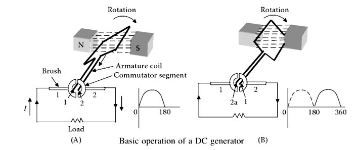
Ques.48. The average power in a pure inductive circuit is __________
- Zero✓
- Maximum
- VI
- V.I.Cosφ
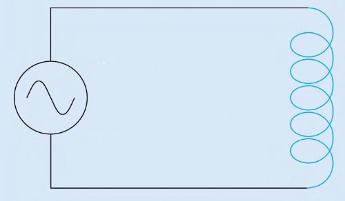
Consider a purely inductive circuit as shown in the figure. In a purely inductive circuit, the current lags the voltage by 90°. To understand this we must have to consider the relationship between applied voltage and the induced voltage. How the current and applied voltage can become 90° out of phase with each other can best be explained by comparing the relationship between the current and induced voltage. As we know that the induced voltage is proportional to the rate of change of the current (speed of cutting action). At the beginning of the waveform, the current is shown at its maximum value in the negative direction. At this time, the current is not changing, so the induced voltage is zero. As the current begins to decrease in value, the magnetic field produced by the flow of current decreases or collapses and begins to induce a voltage into the coil as it cuts through the conductors (Figure.). The greatest rate of current change occurs when the current passes from negative, through zero and begins to increase in the positive direction. Because the current is changing at the greatest rate, the induced voltage is maximum. As current approaches its peak value in the positive direction, the rate of change decreases, causing a decrease in the induced voltage. The induced voltage will again be zero when the current reaches its peak value and the magnetic field stops expanding. It can be seen that the current flowing through the tile inductor is leading the induced voltage by 90°. Because the induced voltage is 180° out of phase with the applied voltage, the current lags the applied voltage by 90°. Or Mathematically we can prove the same Consider the sinusoidal current and voltage waveform. As we know that the voltage leads the current by 90°. i.e I = Imsinωt The value of current will be maximum when ωt = 90° Then I = Imsin90° V = Vmsin(180°) V = 0 Hence when the current will reach its maximum value the voltage will become zero.Pure Inductive circuit
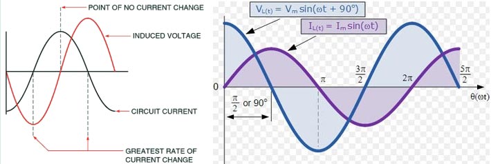
V = Vmsin(ωt + 90°)
I = Im
Ques.49. Which of the following is the most economical method for starting single-phase motor?
- Induction start method
- Capacitor start method✓
- Resistance start method
- Split phase method
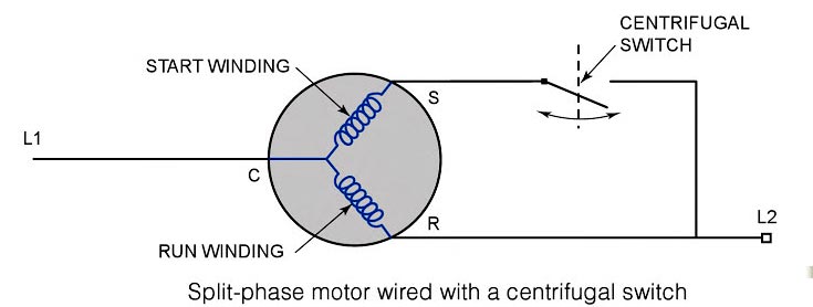
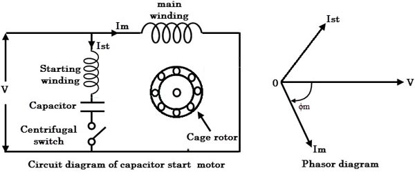
Various method of starting a single-phase motor is Split-Phase Method When two windings that are displaced electrically by 90°, carry currents with a phase difference of 90°, they will produce a rotating magnetic field. The split-phase method also referred to as the induction-star induction-run (ISIR) method, it has a relatively low starting torque compared with the other single-phase motors but more torque than the shaded-pole motor. They range in size from 1/20 horsepower to abort 1/3 horsepower. Split-phase motors get their name from the fact that a single power supply is split between two individual windings — the run and the start — to produce the necessary torque to start the Motor. A split-phase induction motor is provided with the main winding and auxiliary or start winding placed in space quadrature and is connected in parallel to a single-phase supply. The main winding has a low resistance and high reactance whereas the auxiliary winding has a high resistance and low reactance. The auxiliary winding is effective during the starting of the motor and is disconnected from the supply when the motor attains 75 percent of its synchronous speed. A centrifugal switch, S is used to disconnect the auxiliary winding from the source as shown in Fig. Under the normal running condition, only the main winding is effective. The run winding is energized whenever the motor is energized. This winding has a lower resistance than the start winding, which is only in the circuit long enough to help the motor start. For the motor to start, both the start and run windings must be energized. When both windings are energized, the current flows through each of the windings at a different rate, creating a phase shift. This starting method is cheaper than the capacitor start method Capacitor Start Method The capacitor starts motor employs capacitance to split the phase, rather than resistance. The use of capacitance has many advantages. The fluxes in the two phases can be made to have a phase difference of practically 90°, so that the motor becomes essentially a two-phase motor. Since the currents differ by almost 90°, the starting torque is considerably greater than with the usual split-phase motor of the same rating. The capacitance may remain in the circuit continuously so that the power factor of the motor is very nearly unity. The starting torque can be further increased by increasing the capacitor rating. The cost of the capacitor start method is slightly higher than the split-phase method but due to high starting torque and high power factor, this method is the most economical method to start a single-phase motor. Shaded pole motor method The effect of the shaded coil is to retard in time phase a portion of flux in the poles so that there is a sweeping of the flux across the pole face in the direction of the shading of the coil. The fluxes in the unshaded part of the pole and in the shaded part of the pole cut the rotor conductors and induce currents, which in turn produce a torque sufficient to start the motor. The shaded pole produces a weak starting torque and is used with fractional horsepower motors, such as fan motors and shaving motors. The shaded pole motor is the most simply constructed and therefore, the least expensive of the single-phase motors. Repulsion motor start method A common method of obtaining large starting torque is designing the motor so that on starting, it operates as a repulsion motor and when it attains synchronous speed, it is converted into a single-phase induction motor, by some mechanism operated by centrifugal force. It is the most costly method hence this method is replaced by the capacitor start method.
Ques.50. Which efficiency of the battery is more?
- Ampere-hour efficiency✓
- Watt-hour efficiency
- Overall efficiency
- None of the above
The efficiency of a cell can be considered in two ways: The Ah efficiency does not take into account the varying voltages of charge and discharge. The Wh efficiency does so and is always less than Ah efficiency because the average p.d. during discharging is less than that during charging. Usually, during discharge the e.m.f. falls from about 2.1 V to 1.8 V whereas during charge it rises from 1.8 volts to about 2.5 V. The charging voltage for any rechargeable battery is greater than the discharging voltage. The charging voltage is the sum of the battery e.m.f. and the voltage drop due to the battery’s internal resistance. The discharging voltage is the difference between the battery e.m.f. and the voltage drop due to the battery’s internal resistance. Due to the internal resistance of the battery, the discharged energy is always less than the charging energy. Ah efficiency = amp-hour discharge ⁄ amp-hour charge The Ah efficiency of a lead-acid cell is normally between 90 to 95%, meaning that about 100 Ah must be put back into the cell for every 90-95 Ah taken out of it. Because of gassing that takes place during the charge, the Ah available for delivery from the battery decreases. It also decreases (i) due to self-discharge of the plates caused due to local reactions (ii) due to leakage of current because of faulty insulation between the cells of the battery. The Wh efficiency varies between 72-80%. If Ah efficiency is given. Wh efficiency can be found from the following relation: Wh efficiency = (Ah efficiency × average voltage on discharge) ⁄ average voltage on the charge. From the above, it is clear that anything that increases the charge volts or reduces the discharge volts will decrease huh efficiency. Because high charge and discharge rates will do this, hence it is advisable to avoid these. As the average voltage on discharge is always less than the average voltage on charge the watthour efficiency is less than the Ampere hour efficiency.