
Ques.71. Free running and costing periods are generally long in case of
- Mainline service✓
- Urban service
- Sub-urban service
- All of the above
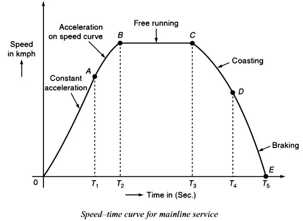
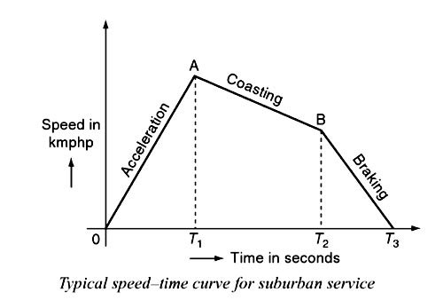
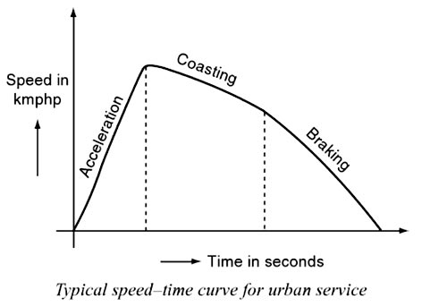
The movement of trains and their energy consumption is most conveniently studied by means of speed-time and speed-distance curves, which show respectively the speed at various times after the start of the run and the speed at various distances from the starting point. The curve that shows the instantaneous speed of the train in kmph along the ordinate and time in seconds along the abscissa is known as the speed-time curve. The curve that shows the distance between two stations in km along the ordinate and time in seconds along the abscissa is known as the speed-distance curve. The area under the speed-time curve gives the distance traveled during, given time internal and slope at any point on the curve toward abscissa gives the acceleration and retardation at the instance, out of the two speed—time curve is more important. The speed-time curve for the mainline service The typical speed-time curve of a train running on the mainline service is shown in Fig. It mainly consists of the following time periods: (i) Constant accelerating period. (ii) Acceleration on speed curve. (iii) Free-running period. (iv) Coasting period. (v) Braking period. Constant acceleration During this period, the traction motor accelerates from rest. The curve OA represents the constant accelerating period. During the instant 0 to T1, the current is maintained approximately constant and the voltage across the motor is gradually increased by cutting out the starting resistance slowly moving from one notch to the other. Thus, current taken by the motor and the tractive efforts are practically constant and therefore acceleration remains constant during this period. Hence, this period is also called the notch up accelerating period or rheostatic accelerating period. The typical value of acceleration lies between 0.5 and 1 kmph. Acceleration is denoted with the symbol ‘ α. Acceleration on speed Curve During the running period from T1 to T2, the voltage across the motor remains constant and the current starts decreasing, this is because cut out at the instant T1 . According to the characteristics of the motor, its speed increases with the decrease in the current and finally, the current taken by the motor remains constant. The acceleration reaches zero for a certain speed, at which the tractive effort excreted by the motor is exactly equaled to the train resistance. This is also known as decreasing the accelerating period. This period is shown by the curve AB. Free running or constant-speed period The train runs freely during the period T2 to T3 at the speed attained by the train at the instant T2. During this speed, the motor draws constant power from the supply lines. This period is shown by the curve BC. The free-running period of Coasting period This period is from T3 to T4, i.e., from C to D. At the instant T3 power supply to the traction, the motor will be cut off and the speed falls on account of friction, windage resistance, etc. During this period, the train runs due to the momentum attained at that particular instant. The rate of the decrease of speed during the coasting period is known as coasting retardation. Usually, it is denoted with the symbol, βc. Braking period The braking period is from T4 to T5, i.e., from D to E. At the end of the coasting period, i.e., at T4 brakes are applied to bring the train to rest. During this period, the speed of the train decreases rapidly and finally reduces to zero. In mainline service, the free-running period will be more, the starting and braking periods are very negligible, since the distance between the stops for the mainline service is more than 10 km. In suburban service, the distance between two adjacent stops for an electric train is lying between 1 and 8 km. In this service, the distance between stops is more than the urban service and smaller than the mainline service. The typical speed—time curve for suburban service is shown in Fig. The speed-time curve for urban service consists of three distinct periods they are: (i) Acceleration. (ii) Coasting. (iii) Retardation. For this service, there is no free-running period. The coasting period is comparatively longer since the distance between two stops is more. The braking or retardation period is comparatively small. It requires relatively high values of acceleration and retardation. Typical acceleration and retardation values are Iying between 1.5 and 4 kmph and 3 and 4 kmph, respectively. Speed-time curve for urban or city service The speed-time curve urban or city service is almost similar to suburban service and is shown in Fig. In this service also, there is no free-running period. The distance between the two stops is less than 1 km. Hence, relatively short coasting and a longer braking period is required. The relative values of acceleration and retardation are high to achieve a moderately high average between the stops. Here, the small coasting period is included to save energy consumption. The acceleration for the urban service lies between 1.6 and 4 kmph. The coasting retardation is about 0.15 kmph and the braking retardation is lying between 3 and 5 kmph. Note:- Free running and costing periods are generally long in case of Mainline service [ninja_tables id=”28815″]SPEED-TIME AND SPEED-DISTANCE CURVES FOR DIFFERENT SERVICES
Speed-time curve for suburban service
Ques.72. Usually wide and very sensitive speed control is required in case of
- Reciprocating pump
- Colliery winders✓
- Centrifugal Blower
- Lathe machines
Colliery winders is a coal mine together with its physical plant and outbuildings. Colliery winders are used for raising coal, lowering and raising of men and material. A large torque is required wound rotor-type induction motors are used. It required very wide sensitive speed control and to control this type of motor ward Leonard method is most suitable. The motors used in coal and mining are classified into two groups. The first group is driven by mine accessories such as compressors, pumps, etc. While the second motors are used for the actual mining process i.e. to drive the cutters, drillers, etc. It is necessary that the motors used for coal and mining must be flameproof. The atmosphere is generally hot with high ambient temperature and also humid. The motors should have humid-proof insulation. The coal cutting or drilling does not require any speed control as the processes are constant speed processes. High starting torque is necessary. The high starting torque squirrel cage motors with double cage are preferred for these applications The mine winder motor may be a D.C motor win Ward Leonard speed control or slip ring motor with rotor resistance starter is preferred.
Ques.73. What is the maximum span upto which the wooden poles can be used?
- 20 m
- 50 m
- 100 m
- 60 m✓
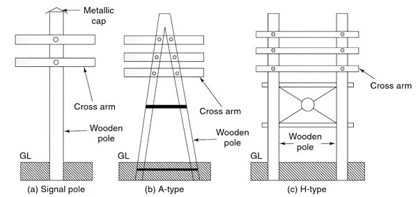
This is one of the simplest forms of the line support. Generally, wooden poles are used. They are cheap, easily available, and have good insulating properties. These poles must be straight, strong, and free from knots. The poles should be properly seasoned to prevent rapid decay because of crakes. An aluminum, zinc, or cement cap is used at the top of the wooden pole to prevent decay due to snow and rain. They are widely used for distribution purposes up to 22 kV and short spans (up to 60 meters). In cities where timber is easily available and the cost of transportation of steel towers is more, single and double pole structures either A or H type are widely used for overhead lines for 130 kV and for the span of 150 meters as shown in Fig. Wooden poles generally rot below the ground level and to prevent this preservative compounds such as creosote oil is used. Advantages of Wooden Poles Disadvantages of Wooden PolesWooden Poles:
Ques.74. In a closed-loop system in which the output is the speed of a motor, the output rate control can be used to
- Limit the torque output of the motor
- Limit the acceleration of the motor
- Limit the speed of the motor✓
- Reduce the damping of the system
Open Loop Control System:- When the action of the system is independent of the output i.e the output has no influence or effect on the control action of the input signal then the system is called the open-loop control system. An Open-loop system is also called the non-feedback system. Closed-Loop Control System:- A closed-loop control system, on the other hand, uses input as well as some portion of the output to regulate the output. Closed-loop systems are also called feedback control systems. In feedback control, the variable required to be controlled is measured. This measurement is compared with a given setpoint. If the error results, the controller takes this error and decides what action should be taken I compensate to remove the error. Errors occur when an operator changes the setpoint intentionally when a process load changes the process variable accidentally. The error could be positive negative. An automatic speed control system of a typical DC motor is illustrated in Fig. The speed of the motor output is a function of both the d.c. motor terminal voltage and the load torque. The machine tool will maintain a constant speed, provided there are no changes to either of these inputs. If the d.c. supply voltage Vs to the regulator is varied, however, then the d.c. motor terminal voltage Vt will be disturbed, and if the load on the motor is changed the current drawn by the motor from the d.c. the regulator will change too. In either circumstance the speed of the motor system outputs will change and, in an open-loop system, there is no feedback to correct the input levels and reset them to the desired settings. The machine tool will, therefore, maintain the new constant speed until either input function is altered. In contrast to open-loop control systems, closed-loop control systems utilize the additional actions of measurement and feedback of the actual output quantity and compare it with the desired reference quantity at an input. Using this feedback the actuator input signal can thereby be changed to achieve the desired output. In closed-loop systems then, the output value has a direct effect upon the input quantity. In the d.c. motor example, a person could be assigned the task of checking the actual speed of the motor (output) and comparing it with the desired reference speed input. Any necessary changes can then be made in order to ensure that the output matches the desired value. The feedback action, therefore, controls the effective input to the dynamic unit.If the speed becomes faster than the desired speed a negative value results as the error signal. The negative value causes the DC motor to reduce in speed and therefore compensate for the excess in speed.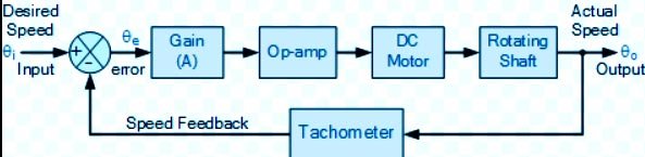
Ques.75. The voltage of a circuit is measured by a voltmeter having input impedance comparable with the output impedance of the circuit thereby causing an error in voltage measurement. This error may be called as
- Gross Error
- Random Error
- The error caused by the loading effect✓
- The error caused by misuse of the instrument
Loading Effects: Loading effects due to an improper way of using the instrument cause serious errors. The best example of such loading effect error is connecting a well-calibrated voltmeter across the two points of high resistance circuit. The same voltmeter connected in a low resistance circuit gives an accurate reading. Thus, the errors due to the loading effect can be avoided by using an instrument intelligently and correctly.
Ques.76. What should be the size of the slide wire of the potentiometer to make it to achieve high accuracy?
- As long as possible✓
- As short as possible
- 1 meter
- Neither too thin nor too thick
A potentiometer is an instrument designed to measure an unknown voltage by comparing it with a known voltage. This known voltage is supplied by a standard cell or through a reference source. The potentiometer makes use of null or balanced conditions for the purpose of measurement. The potential difference across the length of the potentiometer wire is directly proportional to its Length (or) when a steady current is passed through a uniform wire, potential drop per unit length or potential gradient is constant. E ∝ L ⇒ E = φL Where φ is the potential gradient So In the case of longer wire, the fall of potential per unit length is small. In other words, the potential gradient is small. The lesser the potential gradient, the more accurate is the potentiometer.
Ques.77. A network has 10 nodes and 17 branches. then the total number of the independent loop will be
- 9
- 6
- 7
- 8✓
The independent loop in a network L = b-N +1 where b total branches in the network N total number of nodes L = 17-10+1 = 8
Ques.78. If two resistances of 10 Ω and 10 Ω are connected in parallel the equivalent resistance is
- 15Ω
- 5Ω✓
- 1Ω
- 100Ω
When resistance is connected in parallel their equivalent resistance is R = (R1 × R2)/(R1 + R2) R = (10 × 10)/(10 + 10) R = 5Ω
Ques.79. What should be observed when connecting a voltmeter into a DC circuit?
- RMS
- Resistance
- Polarity✓
- Power factor
Precautions to be taken while using a Voltmeter The following precautions must be taken while using a voltmeter: 1) The voltmeter resistance is very high and it should always be connected across the circuit or component whose voltage is to be measured. 2) For using analog voltmeters on DC electricity, it is very important to maintain proper polarity. Most DC power supplies and meters are color-coded to indicate the polarity. Red indicates the positive terminal, and black indicates the negative terminal. The polarities must be observed correctly. The wrong polarities deflect the pointer in the opposite direction against the mechanical stop and this may damage the pointer. If the polarity is reversed when using a digital voltmeter, usually a (- ) minus sign is shown in the display and indicates reversed polarity. However, if you do not reverse the leads, no harm will come to the digital meter. 3) While using the multirange voltmeter, first use the highest range and then decrease the voltage range until sufficient deflection is obtained. 4) Take care of the loading effect. The effect can be minimized by using high-sensitivity voltmeters.
Ques.80. Which of the following capacitors of identical rating will have the smallest dimensions?
- Ceramic capacitor✓
- Paper capacitor
- Aluminum foil capacitor
- Mica Capacitor
Electrolytic Capacitors are generally used in DC power supply circuits due to their large capacitance and small size to help reduce the ripple voltage or for coupling and decoupling applications. Electrolytic’s generally come in two basic forms; Aluminium Electrolytic Capacitors and Tantalum Electrolytic Capacitors. The tantalum and electrolytic capacitors have ratings of 6, 10. 12. 15. 20. 25, 35, 50. 75, I00V, and higher. Paper capacitors: Paper capacitors use paper as the dielectric. They are made of flat strips of metal foil plates separated by a dielectric, which is usually waxed paper. Paper capacitors have values in the picofarad and low microfarad, ranges. The voltage ratings are usually less than 6 V. Paper capacitors arc usually sealed with wax to prevent moisture problems. The voltage rating of capacitors is very important. A typical set of values marked on a capacity might be “10 μF, 50 DCWV.” Such a capacitor h a capacitance of 10 μF and a “dc working voltage” of 50V. This means that a voltage in excess of 50 could damage the plates of the capacitors. Ceramic capacitors: Ceramic capacitors make use of ceramic as the dielectric material. Basically, ceramic materials are fanned from titanium dioxide. Some of the dielectric materials used are barium titanate, magnesium titanic, and zirconium titanate. Ceramic capacitors are produced as tubular, disk, and multilayer (monolithic) capacitors. Disk and tubular ones are inexpensive. Multilayer capacitors are rather expensive but they have small dimensions and low index. The relative permittivity of mica ranges from 3–6(depending upon purity) and the relative permittivity of different types of ceramic ranges from 20–30. Clearly, ceramic capacitors have a higher capacitance. The maximum voltage rating of the ceramic capacitor is 10000 V, while the voltage rating of the mica capacitor is 4000 V.