
Ques.81. 15 minutes rated motors are suitable for
- Light duty cranes✓
- Medium duty
- Heavy-duty cranes
- All options are correct
A short time rating of an electric motor can be defined as the extrapolated overload rating of the motor which it can supply for the specified short time without getting overheated. In this type of duty, the load occurs on the motor during a small interval, and the remains idle for a long time to re-establish the equality of temperature with the cooling medium. The variation of the load against time for short-time duty is shown in Fig. When a motor is used for this purpose, the duration of the load on the motor is less than the heating time constant of the motor or the time required for obtaining thermal equilibrium. The period of rest is sufficient enough to cool the motor to the ambient temperature. The rating of the motor is called a short-time rating. The motors may have 10 minutes, 30 minutes or 60-minute rating based on this criterion. The motor is thermally well utilized. Nowadays the machines are being designed and manufactured for a short duration having sufficient overload torque capability. Usually, such type of short-time duty occurs in bridges, lock gates, and some, other household appliances such as mixies.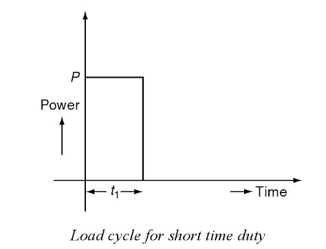
Ques.82. The capacity of Single phase induction motor is limited by
- Pulsating Torque✓
- Uniform Torque
- Non-Uniform Torque
- None of these
The capacity of Single phase induction motor is limited by Pulsating Torque Consider the case that the rotor of the single-phase induction motor is stationary and the stator is connected to a single-phase supply. When a single-phase supply is connected to the stator winding a pulsating or Alternating magnetic field is produced. This pulsating field builds up in one direction, falls to zero and then builds up in the opposite direction. Under this condition, the resultant torque is zero and pulsating magnetic field cannot produce rotation in the rotor. Therefore, a single-phase induction motor is not a self-starting motor. So if the rotor is ‘artificially’ started in one direction or the other, it will continue to rotate in that direction. This initial start is effected by adding a start winding, electrically a few degrees out-of-phase with the main stator winding. The field moves from the start winding to the main winding, and so the rotor receives a pulse start torque. The start winding is switched out of the circuit when the rotor is up to speed. The single-phase induction motor displays similar characteristics to those of the three-phase induction motor. The pulsating torque results from the interactions of the opposite fluxes and m.m.f.’s which cross each other at twice the synchronous speed such as the interaction of the forward flux with the backward rotor m.m.f. and of the backward flux with the forward rotor m.m.f. The interaction of the forward flux with the rotor forward m.m.f. and that of the backward flux with the rotor backward m.m.f. produce the constant torque. Note that the pulsating torque produces no average torque but rather produces a humming effect and makes single-phase motors noisier than polyphase motors. Losses The alternation in field flux would cause excessive eddy current losses in the field core and yoke. The inductances of the field and armature windings cause abnormal voltage drops. So the torque developed is lower. Single-phase ac motors are employed for low-voltage, low-power applications -fractional-kW motors. They operate on the same basic principles as the 3-phase motor, but the pulsating single-phase field produces additional losses, reducing motor torque and the pulsating torque component increases the noise level of the motor. Therefore the capacity of the single-phase induction motor is limited by its pulsating torque hence the size of single-phase motors are limited to 5-hp.
Ques.83. Which among these is a part of the distribution system?
A) Feeders
B) Distributors
C) Service Mains
- Only A
- Only B
- Only C
- A, B &C✓
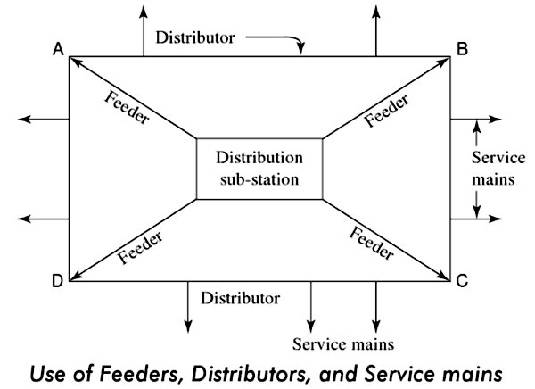
Connection Of distribution Power System The distribution network consists of Feeder:- The lines which transmit electrical power from the generating station to the different substations are feeders. The feeder is a cable that feeds the distributor. There are no tappings on feeders. Distributors:- The electrical power is distributed from the substations with the help of distributors. The distributors can have the number of tappings. Service mains:- The small cables which are used to supply consumers from the distributor are called service mains. Two types of arrangements are made. These are called radial system and ring main system.
Ques.84. Transfer function of a system is G(s) = K/[s2(1 + sT)]. This open-loop system is
- Marginally stable
- Stable
- Conditionally stable
- Unstable✓
Routh-Hurwitz Tests Here are the three tests of the Routh-Hurwitz Criteria. For convenience, we will use N as the order of the polynomial (the value of the highest exponent of s in D(s)). The equation D(s) can be represented generally as follows: D(s) = ao + a1s + a2s2 + ………….+ aNSN Rule 1 Rule 2 Rule 3 As per the necessary condition required for a system to be stable, there must be no missing term in their Characteristic Equation. here the term of s(1) is missing so we can directly say the system is unstable.
Ques.85. Which input yields natural response?
- Ramp Input
- Sinusoidal Input
- Impulse input✓
- Step Input
The homogeneous response of a system is the “natural” response, which represents how energy flows within the system, whenever the system is disturbed from a dynamic equilibrium by a change to the system’s input. The natural response is known as the “unforced” response because the natural response is produced, when the forcing function (also known as the driving function, or input) is turned on or off, or when it changes form, such as from a step to a ramp. The impulse response is the natural or homogeneous response since the particular solution for an impulse response is zero. It is the system’s response to initial conditions with all external forces set to zero. In circuits, this would be the response of the circuit with initial conditions (initial currents on inductors and the initial voltage on capacitors for example) with all the independent voltages set to zero volts (short circuit) and current sources set to zero amps (open circuit). Step response and ramp response in an RL circuit can be obtained by integrating its impulse response successively. Step Input:- This represents the sudden, instantaneous and finite change in the input. Examples are the sudden application of force to a mechanical system, an instantaneous closing of the switch in an electrical circuit, etc. Ramp Input: This represents a linear change in input. The input, i.e. a variable to be measured vanes linearly with time. It changes at a constant rate with respect to time.
Ques.86. The speed of the rotating magnetic field in an induction motor is known as the
- Synchronous speed✓
- Shaft speed
- Slip speed
- Effective speed
The polyphase induction type of motor depends upon the principle of a rotary magnetic field. Polyphase motors using a rotating magnetic field were invented by Nikola Tesla in 1898. When a rotating magnetic field is subjected to a metallic cylinder free to rotate in the field, eddy currents are set up in it. These currents, according to Lenz’s law, try to reduce the relative motion between the cylinder and the field. Therefore the cylinder begins to rotate in the direction of the field. This principle is used in induction motors. Rotating magnetic field of the induction motor runs with a speed of synchronous Speed. Which is given by Ns = 120f/P Let us explain in detail The rotating magnetic field can be defined as the field or flux having constant amplitude but whose axis is continuously rotating in a plane with a certain speed. So if the arrangement is made to rotate a permanent magnet, then the resulting field is a rotating magnetic field. But in this method, it is necessary to rotate a magnet physically to produce a rotating magnetic field. But in three-phase induction motors, such a rotating magnetic field is produced by supplying currents to a set of stationary windings, with the help of three-phase a.c. supply. The current-carrying windings produce the magnetic field or flux. And due to the interaction of three fluxes produced due to three-phase supply, resultant flux has a constant magnitude, and its axis rotates in space, without physically rotating the windings. This type of field is nothing but a rotating magnetic field. A 3-phase induction motor mainly consists of two major parts, the stator and the rotor separated by a uniform air gap. When the 3-phase winding suitably wound on the stator is supplied with a 3-phase balanced ac supply, a uniformly rotating magnetic field of constant magnitude and rotating at synchronous speed is produced. The rotor of an induction motor is placed in a rotating magnetic field. The speed of this rotating magnetic field is known as the synchronous speed (N,). The lines of force of the stator rotating magnetic field cut the rotor conductors and as a result, an alternating emf is induced in these conductors. Due to the relative motion between the rotating magnetic field and the rotor, a voltage is induced in the conductors placed on the rotor. Since the conductors on the rotor form a closed path due to short-circuited end rings (in cage type of rotor) or through external resistance via slip rings (in case of wound rotor) hence the rotor winding for both types of 3-phase induction motors is equivalent to a short-circuited winding The rotating magnetic field developed by the AC current flowing in the stator windings induces a current in the rotor. Due to this the short-circuited turns of the rotor develop eddy currents in the rotating field of the stator. The interaction of the two magnetic fields turns the rotor and drives the motor shaft firmly attached to the rotor by Lorentz force. It is obvious that the rotor speed cannot become equal to the synchronous speed because, in that case, there will be no relative motion between the rotating magnetic field and the rotor, resulting in no induced current in the rotor conductors, and no torque acting on the rotor. Then, the rotor tends to retard. Therefore, there will always be a slight difference between synchronous speed N1 and the speed of the rotor N2.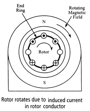
Ques.87. Moving iron meters can be used to measure
- AC
- DC
- Both AC and DC✓
- None of these
This type of instrument is principally used for the measurement of alternating currents and voltages, though it can also be used for d.c. measurements. There are two types of moving-iron instruments. (i) Attraction type in which a single soft-iron vane (or moving iron) is mounted on the spindle and is attracted towards the coil when operating current flows through it. (ii) Repulsion type in which two soft-iron vanes are used; one fixed and attached to the stationary coil while the other is movable (i.e. moving iron) and mounted on the spindle of the instrument. When operating current flows through the coil, the two vanes are magnetized, developing similar polarity at the same ends. Consequently, repulsion takes place between the vanes and the movable vane causes the pointer to move over the scale. The torque produced in moving iron instrument is proportional to the square of the current flowing through the coil T ∝ I2 Hence the deflecting torque depends on the attraction between the field of the coil and the moving iron disc. That is, in an ammeter, the torque is roughly proportional to the current squared. The instrument, therefore, has the square-law response. The deflection is proportional to the mean value of the square of the current hence it can be used to measure both AC and DC quantity. When used on AC, it indicates the RMS or effective value of current (or voltage).Moving – Iron (M.l.) Ammeters and Voltmeters
Ques.88. The material used for the magnetic circuit where the high value of flux density required is
- Cast iron
- Soft steel
- Ferro Cobalt✓
- Gray cast iron
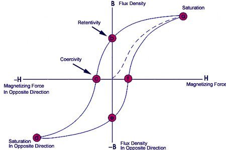
Residual induction: Residual induction is the residual flux density remaining in a saturated magnetic material after the magnetizing force has been withdrawn. It represents the maximum flux output from the magnet that occurs at zero air gap. or The residual induction is any magnetic induction that remains in a magnetic material after removal of an applied magnetic field Remanence: Remanence is defined as the magnetic induction that remains in a magnetic circuit after the withdrawal of an applied magnetizing force. Coercive Force – The amount of reverse magnetic field which must be applied to a magnetic material to make the magnetic flux return to zero. Properties of the material of a permanent magnet : (1) It should have high retentivity so that it remains magnetized in the absence of the magnetizing field. (2) It should have high saturation magnetization. (3) It should have high coercivity so that it does not get demagnetized easily. Hence, these materials cannot be easily magnetized and demagnetizer Hard magnetic materials are used to produce permanent magnets. Hysteresis losses are of no significance here as no repeated reversals of magnetization are involved in a permanent magnet. The permanent magnets must have high residual induction B. and large coercive field Hc. The area of the hysteresis loop between Br and Hc represents the energy required to demagnetize a permanent magnet. The maximum value of this area (= BrHr) called the energy product, must be as large as possible for permanent magnets. As steel and alnico have high coercivity, therefore, they are used for making permanent magnets. The metals in Alnico magnets are indicated by the pairs of letters making up the name, Aluminum, Nickel, and Cobalt.
Ques.89. Which of the following determines total power in a series circuit?
- Source voltage times the current✓
- The total voltage applied to the circuit
- Current flowing through a switch
- Average of the wattage consumed by each resistor
The total power of the in series circuit is given the current times of source voltage. PTOTAL = Vs×Is Vs: source voltage Is: source current
Ques.90. The voltage applied across a ceramic dielectric produces an electrostatic field 100 times greater than in air. The dielectric constant, of the ceramic equals
- 50
- 100
- 100/3
- 1/100✓
Since the voltage across a dielectric Capacitor. V= 1/c ∫ i(t) dt sicne C = ε A/d C is directly proportional to ε ( dielectric constant). In turn, Voltage is Inversely proportional to the dielectric constant. hence the dielectric constant, of the ceramic equal to 1/100.