
SSC JE 2016 Electrical question paper with solution(Set-2)| MES Electrical
Ques.1. Steel poles are generally used for transmission lines because
(A) It has more mechanical strength and more life.
(B) It occupies less space and gives a better appearance.
(C) It has a high cost.
Which of the above provided reasons is/are correct.
- Only A
- Only B
- Only C
- Both A and B✓
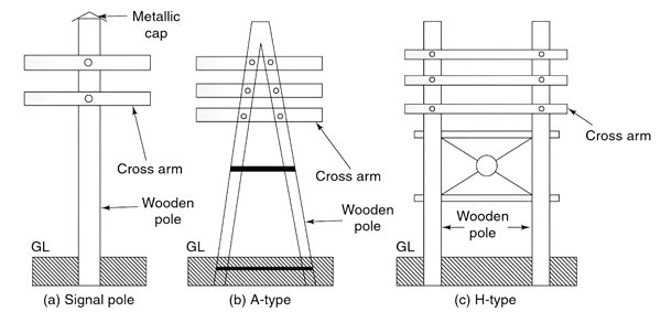
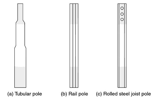
Main components of the overhead lines: The various components of the overhead transmission line are as under: Various conductors used in the transmission lines are as follows: Various line supports used in the transmission lines are as follows: Various types of insulators are used depending on the line voltage and requirement which art as under: LINE SUPPORTS The main function of the line support is to support the conductors to keep them at suitable heights from the ground. Hence, in overhead lines, various types of supporting structures are used such as poles and towers which are called line supports. Generally, line supports have the following properties: (i) Good mechanical strength (ii) Lightweight (iii) Cheap (iv) Longer life Various types of line supports are used in overhead transmission and distribution systems. The selection of line support depends on many factors such as cost, the span of the line, line voltage, local conditions, etc. The various types of line supports are as follows: This is one of the simplest forms of the line support. Generally, wooden poles are used. They are cheap, easily available, and have good insulating properties. These poles must be straight, strong, and free from knots. The poles should be properly seasoned to prevent rapid decay because of crakes. An aluminum, zinc, or cement cap is used at the top of the wooden pole to prevent decay due to snow and rain. They are widely used for distribution purposes up to 22 kV and short spans (up to 60 metros). In cities where timber is easily available and the cost of transportation of steel towers is more, single and double pole structures either A or H type are widely used for overhead lines for 130 kV and for the span of 150 meters as shown in Fig. Wooden poles generally rot below the ground level and to prevent this preservative compounds such as creosote oil is used. Advantages of Wooden Poles Disadvantages of Wooden Poles The drawbacks of wooden poles are absent in the steel poles and hence they are generally used as a substitute to the wooden poles. They have better mechanical strength and longer life. They can be used for a long span. These poles are used for distribution purposes in urban areas. These types of poles are generally galvanized or painted to increase their life. These poles are shown in Fig. Generally, three types of steel poles are available as follows: Advantages of Steel Poles Disadvantages of Steel Poles
Wooden Poles:
Steel Poles
Ques.2. In the case of traveling cranes, the motor preferred for boom hoist is ______
- Slip Ring Induction Motor✓
- Squirrel cage induction motor
- Synchronous Motor
- Single-phase motor
A hoist having a spar projecting from the mast to support and guide the load is called Boom Hoist. For crane travel, trolley travel and boom hoist of traveling crane require high starting torque and constant speed in operation. Hence slip ring induction motor is preferred. In SLIP RING induction motor the ends of the rotor windings are externally connected by a variable rheostat (resistance is varied in order to give it proper starting and running current). So more the resistance, more the torque. When we add resistance to the rotor the torque is high, the slip is high and the current is reduced. With the correct value of (usually) resistance inserted in the rotor circuit, a near-unity relationship between torque and supply current at the start can be achieved, such as 100%full load torque (FLT), with 100% full load current (FLC) and 200% FLT with 200 percent FLC. This is comparable with the starting capability of the dc machine. Not only high starting efficiency but also smoothly controlled acceleration historically gave the slip ring motor a great popularity for lift, hoist and crane applications.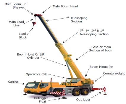
Ques.3. The purpose of skewing of rotor slots in an induction motor is to ________
- Reduce magnetic hum
- Increase the distribution factor
- Reduce the locking tendency of the rotor✓
- Increase the air gap
There are two primary sources of noise in polyphase induction motors: magnetically induced noise, called Magnetic noise, and noise Induced by the flow of air, called Windage noise. The level of noise of magnetic origin is variable because it depends on the design, the load, the speed, and the power supply. For low-speed machines, magnetic noise almost always prevails. It is generated by electromagnetic forces, which occur between the stator and the rotor. They produce vibrations of the machine, mainly the stator. When the frequencies of the electromagnetic forces are close to the resonance frequencies of the stator, the vibrations and the noise are amplified. The magnetic noise of rotating machines can easily be distinguished from other noises by cutting off the electric supply: the magnetic noise is immediately stopped while aerodynamic and mechanical noises decrease slowly with the speed. Rotor conductors are skewed because of the following main reasons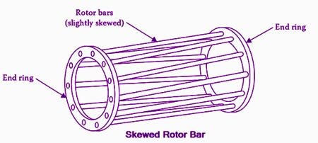
Ques.4. What is the factor of safety used for current ratings in a power installation?
- 1.25✓
- 1
- 2
- 2.5
The ratio of the maximum permissible stress to the allowable stress is called factor of safety. The factor of safety, FOS = Maximum stress/Working stress The value of factor of safety varies with the type of load. It is least with gradually applied load and maximum for impact type load. In order to be on the safe side, for the selection of wires, the maximum current in the system is multiplied by a factor of 1.25. It means the current is increased by 25% of the maximum value and then wires are chosen to carry this particular current.
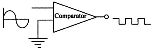
Ques.5. One input terminal of the high gain comparator circuit is grounded and a sinusoidal voltage is applied to the other input. The output of the comparator will be
- Half rectified sinusoidal
- Full rectified sinusoidal
- Triangular wave
- Square wave✓
The op-amp in open loop configuration can be used as a basic comparator. When two inputs are applied to the open-loop op-amp then it Compares the two inputs. Depending upon the comparison, it produces an output voltage which is either positive saturation voltage (+Vsat) or negative saturation voltage (−Vsat). A comparator is a circuit that compares a signal voltage applied at one input of an op-amp with a known reference voltage at the over-input and produces either a high or a low output voltage, depending on which input is higher. As comparator output has two voltage levels, either high or low, it is not linearly proportional to the input voltage. There are two types of comparator circuits which are, 1. Non-inverting comparator 2. Inverting comparator In this comparator, the input voltage is applied to the non-inverting terminal and no reference voltage is applied to the over terminal. So inverting terminal is grounded. The input voltage is denoted as Vin, while the voltage applied to the over terminal with which Vin is compared is denoted as Vref. In the basic comparator, Vref = 0 V. The basic non-inverting comparator is shown in Fig. In the non-inverting comparator, if Vin, is greater than Vref then the output is +Vsat i.e almost equal to +VCC (Collector supply voltage). While if Vin is less than Vref then the output is −Vsat i.e. almost equal to −VEE(Emitter supply Voltage). When the non-inverting input is higher or greater than the inverting input voltage, the output of the comparator is high and when the non-inverting voltage is less than the latter output of the comparator is low. If the inverting terminal is grounded, even the slightest input voltage at the non-inverting terminal is enough to saturate the opamp. Therefore, the output is at positive saturation as soon as the voltage at the non-inverting terminal increases slightly above zero. When the noninverting input goes above ground (zero volts), the output will be driven to positive saturation by the high voltage gain of the op-amp. When the noninverting input drops below ground, the output switches to negative saturation. So the output is a square wave.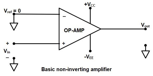
Ques.6. What is the efficiency of the transformer compared with that of the electrical motors of the same power?
- Very less
- Much Higher✓
- Less
- Equal
As the Transformer is a static device, it does not have any rotating parts hence the mechanical losses are absent which increases the efficiency of the transformer. Transformer efficiency is generally greater than 90 – 95%, while that of the motors is about 70 to 75%.
Ques.7. Which of the following is essential for the reciprocity theorem to be applicable?
- Linearity
- Bilateralism
- No initial History
- All of the above✓
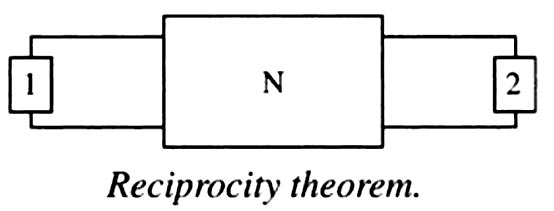
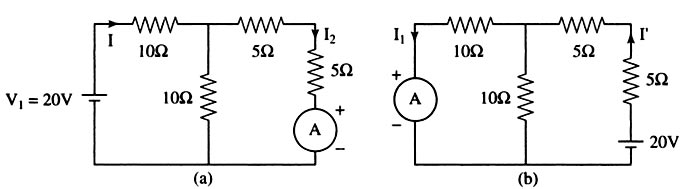
Linear circuit:- A linear circuit is an electric circuit in which circuit parameters (Resistance, inductance, capacitance, waveform, frequency, etc) are constant. In other words, a circuit whose parameters are not changed with respect to Current and Voltage is called Linear Circuit. Bilateral Circuit:- A circuit Whose characteristics are the same in either direction of the current flow is called a bilateral circuit. The electrical transmission line is an example of the bilateral circuit as it performs its functions equally Bell in both directions. Whereas, a diode is a unilateral element, unlike the bilateral element in which the direction of flow of current affects circuit behavior. In forward bias, it has the least resistance and allows maximum current through it. In reverse bias, it offers high resistance to the flow of current. The reciprocity theorem is applicable to bilateral networks. A bilateral network is made up of bilateral elements. The theorem is stated as follows: The interchange of an ideal voltage source and an ideal ammeter in any passive, linear, bilateral network, will not change ammeter reading. Similarly, The interchange of an ideal current source and an ideal voltmeter in any passive, linear, bilateral circuit, will not change voltmeter reading. Consider Fig. Here, N is a passive linear network. Suppose an ideal voltage source, V1 volts, is inserted in branch 1 and it produces a current I2 in branch 2, then if the voltage source is inserted in branch 2, with V2 volts, and the current in branch 1, I1, is measured, it will satisfy the following relationship: V1/I2 = V2/I1 The reciprocity theorem cannot be applied when dependent sources are present. Consider the figure (a) and calculating the current I I = 20 ⁄ [10 + (10 || 10] = 1.333 A I2 = I/2 = 0.667A Now the source and the ammeter are interchanged as shown in the fig.b I” = 20 ⁄ [5+5 (10 || 10)] = 1.333 A I1 = I”/2 = 0.667A I2 = I1, Hence reciprocity theorem is verifiedReciprocity theorem
Verification of reciprocity theorem
Ques.8. Magnetic recording tape is most commonly made from _________
- Ferric oxide✓
- The small particle of iron
- Silicon-iron
- Any of the above
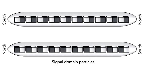
Magnetic tape is a thin strip of plastic, coated on one side with a film of tiny permanent magnets. Each of these permanent magnets has a north magnetic pole at one end and a south magnetic pole at the other. During recording, a strong magnetic field can swap the poles of these particles, altering the tape in a way that can be detected during playback. Magnetic recording can either be analog, as in the audio recording of signals on magnetic tape or dismal recording, as used in the storage of information of data on magnetic disks and tapes for computer applications. There are three major types of magnetic solids, ferromagnetic, antiferromagnetic, and ferrimagnetic, distinguished by the ordering of their individual magnetic atoms. Iron, cobalt, nickel, and chromium dioxide are ferromagnetic solids, meaning that each atom’s magnetic dipole is aligned with those of its neighbors. Chromium is an antiferromagnetic solid, in which the atoms’ magnetic dipoles point in alternating or gradually varying directions and completely cancel one another. Ferrite (γ-iron oxide) and barium ferrite are ferrimagnetic solids, meaning that their atoms’ magnetic dipoles alternate back and forth but, because they have different strengths, don’t cancel one another completely. Both ferromagnetic and ferrimagnetic materials can be used to make permanent magnets. Common plastic sheet magnets usually contain barium ferrites, which are ferrimagnetic substances. Most plastic magnetic recording tapes, however, are coated with iron or other ferromagnetic materials. There isn’t any profound reason for these choices; they’re the consequences of technical and practical concerns. Magnetic recording media use a different type of hard magnetic material—tiny elongated particles of the γ-iron oxide, chromium dioxide, cobalt-coated iron oxide, or pure iron. Each of these particles is so small that it contains only a single magnetic domain. It has a north pole at one end and a south pole at the other, because that arrangement permits the opposite poles of adjacent magnetic atoms to be as close together as possible and minimizes the particle’s total magnetic potential energy. With its magnetization pointing along with its cigar shape, the particle is in a stable magnetic equilibrium: if something disturbs its magnetization direction, it will experience restoring effects that return its magnetization to that equilibrium direction. The most widely used magnetic recording materials are γ-Fe2O3 (Gamma ferric oxide) and cobalt-doped γ-Fe2O3. Each of these particles is a tiny permanent magnet that can’t be demagnetized. It’s always magnetized in one direction or the other along its length. However, the particle’s magnetic poles can be interchanged by exposing it to a strong magnetic field. The particle itself won’t flip, just its magnetic poles. This behavior makes such a particle ideal for magnetic recording. A magnetic recorder can choose a particle’s magnetic orientation during recording and expect it to remain that way for an extremely long time.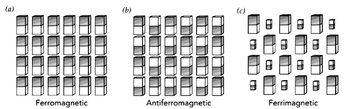
Ques.9. Kirchoff’s current law is applicable to _____
- Electronic circuit
- Network junction✓
- Closed loop in a network
- Electrical circuit
Kirchhoff’s Current Law (KCI ) or Kirchhoff’s Junction Rule. This law is based on the conservation of charge and may be stated as under: The algebraic sum of the currents meeting at a junction in an electrical circuit is zero. An algebraic sum is one in which the sign of the quantity is taken into account. For example, consider four conductors carrying currents I1, I2, I3, & I4 and meeting at point O as shown in Fig If we take the signs of currents flowing towards point O as positive, then currents flowing away from point O will be assigned negative sign. Thus, applying Kirchhoff’s current law to the junction O we have, (I1) + ( I2) + (−I3) + (−I4) = 0 i.e., Sum of incoming currents = Sum of outgoing currents. Therefore, Kirchhoff’s current law may also be stated as under: The sum of currents flowing towards any junction in an electrical circuit is equal to the sum of currents flowing away from that junction. Kirchhoff’s current law is rightly called the junction rule. Kirchhoff’s current law is true because electric current is merely the flow of free electrons and they cannot accumulate at any point in the circuit. This is in accordance with the law of conservation of charge. Hence, Kirchhoff’s current law is based on the law of conservation of charge.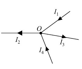
or
(I1) + ( I2) = (−I3) + (−I4)
Ques.10. The materials having low retentivity are suitable for making ______
- Permanent magnet
- Temporary Magnet✓
- Any of the above
- None of the above
The value of the intensity of magnetization of a material when the magnetizing field is reduced to zero is called retentivity or residual magnetism of the material. If the material has high retentivity it will remain magnetized in the absence of the magnetizing field. For making temporary magnets the material should possess low retentivity such as electromagnets.