
Ques.21. What is the maximum length of the flexible conduit in the motor installation? (SSC-2016)
- More than 5 meter
- Less than 1.25 meter
- Less than 2.25 meter
- Less than 3.25 meter
Answer.2. Less than 1.25 meter Explanation:- An electrical conduit is a tube used to protect and route electrical wiring in a building or structure. The electrical conduit may be made of metal, plastic, fiber, or fired clay. Most conduit is rigid, but flexible conduit is used for some purposes. A motor connection is the means by which the power leads are terminated to a motor. From the estimator’s perspective, the motor terminations must also account for connecting the flexible conduit and fittings from the rigid conduit to the motor terminal box at its use point. Flexible conduit to motors serves four functions. According to the National electric Code (NEC), the NEC does restrict the length of the flexible metal conduit of the motor leads between the motor and required junction box to a maximum of 6 ft(1.8 m) to limit the ground return path.
Ques.22. A three-phase induction motor is analogous to (SSC-2016)
- Generator
- Rotating transformer
- Rotating Motor
- Rotating converter
Answer. 2. Rotating Transformer Explanation:- Analysis of the transformer model is very easy to visualize then induction motor so, the induction motor is generalized as a transformer because of the following reasons : Because of the above reasons Induction motor is called two windings transformer with secondary short-circuited.
Ques.23. For the production of induced e.m.f, the field system of an electric machine____. (SSC-2016)
- Must be on the rotor
- Must be on the stator
- May be on rotor and stator
- None of the above
Answer.3. May be on rotor and stator Explanation:- BASIC PRINCIPLES OF ELECTRICAL MACHINES In any machine, the currents in all the windings combine together to produce the resultant flux. The field system produces flux. Voltages are induced in the windings such as those of an armature. When the armature carries current, the interaction between the flux and the current produces torque. Current produced by the relative motion of stator/rotor conductor or magnet is called induced current, set up by an induced electromotive force or EMF. EMF is produced when a current-carrying conductor placed in a rotating magnetic field. Where either field is rotating or conductor. These are the basic facts on which the action of the machine depends. The windings of the electrical machines are mainly of three types: TYPES OF ELECTRICAL MACHINES The type of machine depends on how a particular type of combination of the above windings is used on the stator and the rotor. A synchronous machine has a coil winding and a polyphase winding. Generally, the polyphase winding is on the stator while the coil winding is on the rotor. The coil winding on the rotor produces a field and with the rotation of the rotor, this moves in space at the speed of the rotor. The voltage will be induced in the staler polyphase winding (three-phase). The magnitude of the voltage depends on the strength of the de field and the frequency corresponding to the speed of the rotor when driven as a generator. In the case of motor action, the polyphase winding is supplied with three-phase currents. This produces a rotating field in the airgap. This, when it reacts with the dc field produced by the current in the rotor, makes the machine run as a motor at synchronous speed. The construction of the field system may be on the stator or the rotor. A dc machine has a coil winding for the poles on the stationary part. This produces the stationary field in the space in the air gap due to dc in the field windings wound on the poles. The armature or the rotor has a commutator type of winding with stationary brushes for connecting to the external circuit. The machine can work as a motor or as a generator, depending on the current input to or output from the armature. An induction machine has a polyphase winding both on the stator and the rotor. The three-phase winding on the stator produces a rotating magnetic field. This is cut by the closed circuit of the rotor, thereby producing an induced voltage in the winding due to the transformer action. This produces current in the winding which reacts with the flux to produce torque. The machine runs as an induction motor on the induction principle.
Ques.24. 15 minutes rated motors are suitable for (SSC-2016)
- Light duty cranes
- Medium duty
- Heavy-duty cranes
- All option are correct
Answer.1. Light duty cranes Explanation:- A short time rating of an electric motor can be defined as the extrapolated overload rating of the motor which it can supply for the specified short time without getting overheated. In this type of duty, the load occurs on the motor during a small interval and the remains idle for a long time to re-establish the equality of temperature with the cooling medium. The variation of the load against time for short-time duty is shown in Fig. When a motor is used for this purpose, the duration of the load on the motor is less than the heating time constant of the motor or the time required for obtaining thermal equilibrium. The period of rest is sufficient enough to cool the motor to the ambient temperature. The rating of the motor is called a short-time rating. The motors may have 10 minutes, 30 minutes or 60-minute rating based on this criterion. The motor is thermally well utilized. Nowadays the machines are being designed and manufactured for short duration having sufficient overload torque capability. Usually, such type of short-time duty occurs in bridges, lock gates, and some, other household appliances such as mixies.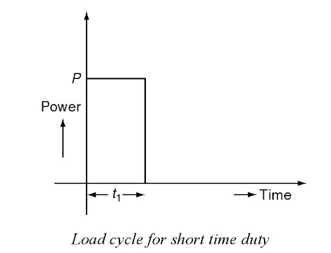
Ques.25. The speed of the rotating magnetic field in an induction motor is known as the (SSC-2016)
- Synchronous speed
- Shaft speed
- Slip speed
- Effective speed
Answer.1. Synchronous speed Explanation:- The polyphase induction type of motor depends upon the principle of a rotary magnetic field. Polyphase motors using a rotating magnetic field were invented by Nikola Tesla in 1898. When a rotating magnetic field is subjected to a metallic cylinder free to rotate in the field, eddy currents are set up in it. These currents, according to Lenz’s law, try to reduce the relative motion between the cylinder and the field. Therefore the cylinder begins to rotate in the direction of the field. This principle is used in induction motors. Rotating magnetic field of induction motor runs with a speed of synchronous Speed. Which is given by Ns = 120f/P Let us explain in detail The rotating magnetic field can be defined as the field or flux having constant amplitude but whose axis is continuously rotating in a plane with a certain speed. So if the arrangement is made to rotate a permanent magnet, then the resulting field is a rotating magnetic field. But in this method, it is necessary to rotate a magnet physically to produce a rotating magnetic field. But in three-phase induction motors, such a rotating magnetic field is produced by supplying currents to a set of stationary windings, with the help of three-phase a.c. supply. The current-carrying windings produce the magnetic field or flux. And due to the interaction of three fluxes produced due to three-phase supply, resultant flux has a constant magnitude and its axis rotating in space, without physically rotating the windings. This type of field is nothing but rotating; magnetic field. A 3-phase induction motor mainly consists of two major parts, the stator and the rotor separated by a uniform air gap. When the 3-phase winding suitably wound on the stator is supplied with 3-phase balanced ac supply, a uniformly rotating magnetic field of constant magnitude and rotating at synchronous speed is produced. The rotor of an induction motor placed in a rotating magnetic field. The speed of this rotating magnetic field is known as the synchronous speed (N,). The lines of force of the stator rotating magnetic field cut the rotor conductors and as a result, an alternating emf is induced in these conductors. Due to the relative motion between the rotating magnetic field and the rotor, a voltage is induced in the conductors placed on the rotor. Since the conductors on the rotor form a closed path due to short-circuited end rings (in cage type of rotor) or through external resistance via slip rings (in case of wound rotor) hence the rotor winding for both types of 3-phase induction motors is equivalent to a short-circuited winding The rotating magnetic field developed by the AC current flowing in the stator windings induces a current in the rotor. Due to this the short-circuited turns of the rotor develop eddy currents in the rotating field of the stator. The interaction of the two magnetic fields turns the rotor and drives the motor shaft firmly attached to the rotor by Lorentz force. It is obvious that the rotor speed cannot become equal to the synchronous speed because, in that case, there will be no relative motion between the rotating magnetic field and the rotor, resulting in no induced current in the rotor conductors, and no torque acting on the rotor. Then, the rotor tends to retard. Therefore, there will always be a slight difference between synchronous speed N1 and the speed of the rotor N2.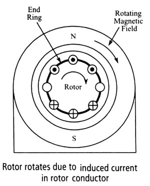
Ques.26. Light duty cranes are generally used in (SSC-2016)
- Automobile workshop
- Pumping Station
- Power Houses
- All of the above
Answer.4. All of the above Explanation:- Classification of Cranes Cranes for foundries, steelworks, and power stations generally require creep speeds on hoist motion for accurate load spotting. Cranes for material handling plants should be designed for higher operating speeds and duty cycles than any general workshop cranes. For steelworks, cranes must be selected to operate round the clock with higher operating speeds and low creep speed. The classification of various types of cranes is mainly based on the following factors: (i) Nature of the work it has to perform, e.g. handling of hot ladles, for the transport of ingots, for the handling of raw materials, etc. (ii) The duty factor: This is the time it has to work compared to the total working period of the shop and the frequency of starting the crane. In a steel plant, they may be divided into 4 groups: (a) Light duty cranes (15% duty factor), e.g. cranes for compressor plant, refrigeration plant, power plant, Automobile workshop, etc. The electrical switching on the operation of light-duty cranes is 60 Per Hour. (b) Medium duty cranes (25% duty factor), e.g. handling materials in auxiliary and repair shops. The electrical switching on the operation of light-duty cranes is 120 Per Hour. (c) Heavy-duty cranes (40% duty factor): The cranes of foundries, forging shops, cast houses, production Ime cranes. The electrical switching on the operation of light-duty cranes is 240 Per Hour. (d) Continuous duty cranes (above 40% duty factor): These are for the major part of production line: cranes for bulk material handling, soaking pit cranes, charging cranes. The electrical switching on the operation of light-duty cranes is 300 to 720 Per Hour.
Ques.27. In an induction motor, if the rotor resistance is equal to stand-still reactance then the maximum torque is (SSC-2016)
- Equal to starting torque
- Less than the starting torque
- More than the starting torque
- None of these
Answer.1. Equal to starting torque Explanation:- The starting torque of induction motor [latex]\begin{array}{l}{T_s} = \dfrac{{K{\rm{ }}{E_2}^2{\rm{ }}{R_2}}}{{{R_2}^2 + {X_2}^2}}\\\\{\text{On diffrentiating the above equation}}\\\\\dfrac{{dt}}{{d{R_2}}} = K\left( {\dfrac{1}{{{R_2}^2 + {X_2}^2}} + \dfrac{{{R_2}\left( {2{R_2}} \right)}}{{{{\left( {{R_2}^2 + {X_2}^2} \right)}^2}}}} \right)\\\\{\rm{On Solving}}\\\\{R_2}^2 + {X_2}^2 = 2{R_2}\\\\or\\\\{R_2} = {X_2}\end{array}[/latex] Maximum starting torque is obtained when the slip is equal to the ratio between the rotor resistance (R2) and the rotor inductive reactance (X2). This slip is also known as slip at maximum torque, labelled as Sm.
Ques.28. Why is the air gap between the yoke and armature of an electric motor kept smaller? (SSC-2016)
- To achieve a stronger magnetic field
- To avoid overheating of the machine
- To make the station easier
- None of these
Answer.1. To achieve a stronger magnetic field Explanation:-
Ques.29. What is the effect produced by the electric current in an electric motor? (SSC-2016)
- Magnetic effect only
- Magnetic as well as the heating effect
- Heating effect only
- Heating as well as the chemical effect
Answer.2. Magnetic as well as the heating effect Explanation:- Any movement of electricity, or flow of CURRENT, through any conductor causes two things to happen: Heating Effect:- On flowing of electric current in any conductor carrying resistance, free electrons colliding with the atoms of conductor and in this collision the main portion of the kinetic energy of electrons is transferred to the atoms by which the internal kinetic energy of the conductor increases, so its temperature increases. This change of electrical energy into heat energy is called the heating effect of electric current. Magnetic Effect:- The term “magnetic effects of current”mean that ” a current flowing in a wire produces a magnetic field around it”. The magnetic effect of current was discovered by Oersted found that a wire carrying current was able to deflect a magnetic needle. It concludes that a current flowing in a wire always gives rise to a magnetic field around it, the electric motor, telephone, and radio, all utilize the magnetic effect of current. An electric motor also uses the effect of flowing current to produce a magnetic field. In a motor, the magnetic field that is produced by electricity interacts with another magnetic field to produce a torque. Usually, in small motors, the wire is coiled around an assembly located in the center of the motor called a rotor or armature. The outside assembly of the motor is stationary and lined with permanent magnets and called a stator. As current flows through the wire wound around the rotor, the magnetic field that is produced interacts with the magnetic field of the stator and the torque causes the rotation to result. As the wire assembly rotates, an electrical connection is made through a conductive ring and brush.
This effect is utilized in the instruments producing heat and light viz electric bulb heater, electric iron, electric arc etc. In these instruments, the electric energy changes into heat energy. This effect is also responsible for wasteful energy losses, due to heat transfer away from a conductor into its surroundings.
Ques.30. If the stator voltage of a squirrel cage induction motor is reduced to 50 percent of its rated value, the torque developed is reduced by how many percentages of its full load value? (SSC-2015)
- 50%
- 25%
- 75%
- 57.7%
Answer.3. 75% Explanation:- Squirrel cage induction motor has a very rugged construction, the three-phase squirrel-cage motor is capable of handling the starting current without any damage to winding. However very large motors may cause line drops, which may affect other equipment operating from the same system For such installations, reduced voltage starters a used. The reduced voltage limits the starting current to a lower value. Starting squirrel cage induction motor under reduced voltage may be reduced the starting voltage considerably. From the torque equation of a three-phase induction motor, the starting torque is approximately proportional to the square of the applied voltage i.e T ∝ V2 By reducing the voltage by 50% ( reducing voltage by 1/2) than T = (1/2)2 T = 1/4 = 25% Hence by reducing the voltage by 50%, the torque is reduced to 25% and 75% of full load value.