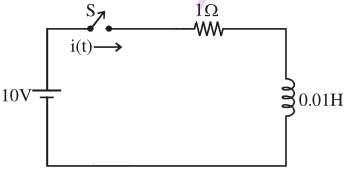
Ques.130. After closing the switch ‘s’ at t = 0, the current i(t) at any instant ‘t’ in the network shown in the figure: (SSC-2014, M-Shift)
10 – 10 e-100t
10 + 10 e100t
10 – 10 e100t
10 + 10 e-100t
Answer.3. 10 – 10 e100t
Explanation
Time constant τ in series LR circuit is
τ =L/R = 0.01/1 = 0.01
Under steady state condition, L is short-circuited then
Io = V/R =10A
Now the instantaneous current i(t) is
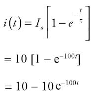
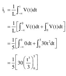
Ques.131. The voltage across 5-H inductor is
Find the energy stored at t = 5 s. Assume zero initial current (SSC-2014, M-Shift)
312.5 kJ
0.625 kJ
3.125 kJ
156 .25 kJ
Answer.4. 156.25 kJ
Explanation:-
Energy stored in inductor “E” = 1/2(LI2)
Voltage across inductor E(l) = L di(t)/dt
or i(t) = 1/L di(t)/dt
= 30/5 x 125/3 = 250A
Energy stored in an inductor = (5 x 2502)/2 = 156.25 kJ
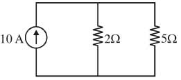
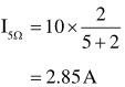
Ques.132. Find the current through 5Ω resistor: (SSC-2014, M-Shift)
3.5 A
7.15 A
5 A
2.85 A
Answer.4. 2.85 A
Explanation:-
By applying current division Rule
Ques.133. An isolator is used in series with air blast circuit Breaker employed at UHV lines because (SSC-2014, M-Shift)
CB life is enhanced with the use of isolator
Current to be interrupted will be large
Gap between CB contacts is small so an isolator is used to switch off voltage
Gap between CB poles is small
Answer.3. Gap between CB contacts is small so an isolator is used to switch off voltage
Explanation:-
An air-blast circuit breaker is small in size, because of the growth of dielectric strength is so rapid (which final contact gap needed for arc extinction is very small) so isolator is used to switch off the voltage.
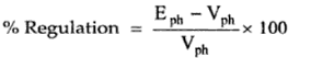
Ques.134. Regulation of an alternator supplying resistive or inductive load is (SSC-2014, M-Shift)
Infinity
Always Negative
Always Positive
Zero
Answer.3. Always Positive
Explanation:-
The voltage regulation of an alternator is defined as the change in its terminal voltage when the full load is removed, keeping field excitation and speed constant, to the rated terminal voltage.
Where Vph = Rated terminal voltage
Eph =No load-induced e.m.f
An increase in the load current in a pure resistive load causes a decrease in the output voltage. For an inductive load, an increase in the load current causes a greater voltage drop as compared to the resistive load. Therefore for inductive and resistive load conditions, there is always a drop in the terminal voltage hence regulation values are always positive.
In the case of leading load that means capacitive load, the effect of armature flux on main field flux is magnetizing i.e, the armature flux is adding up with the main field flux. Since it is adding up, the total induced emf(Vph) will also be more than the induced emf at no load(Eph).Hence the regulation is negative
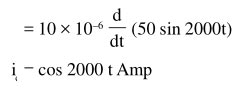
Ques.135. If a 10 μF capacitor is connected to a voltage source with v(t) 50sin2000tV, then the current through the capacitor is _________ (SSC-2014, M-Shift)
106 cos 2000t
5 x 10⁻⁴ cos 2000 t
cos 2000t
500 cos 2000 t
Answer.3. cos 2000t
Explanation:-
The current flowing through the capacitor is given by
I(t) =Cdv(t)/dt
Where I(t) is instantaneous current
C = capacitance in farad
dv/dt =instanaeous rate of voltage changed
Ques.136. In a series resonance circuit, the impedance at half power frequencies is: (SSC-2014, M-Shift)
2R
R/√2
√2R
R/2
Answer.3. √2R
Explanation:-
In series resonance circuit Z = R = V/Im
Half power frequency is the frequency when the magnitude of voltage or current is decreased by the factor of 1/√2 from its maximum value. (Also known as cut-off frequency)
Therefore at half power frequency
I = Im/√2
Now impedance at half power frequency
= V/Im/√2 = √2V/Im =√2R
Ques.137. A circuit with a resistor, inductor, and capacitor in series is resonant of fo Hz. If all the component values are now doubled the new resonant frequency is (SSC-2014, M-Shift)
fo/4
2fo
fo
fo/2
Answer.4. fo/2
Explanation:-
The resonant frequency of LC is:
fo = 1/2π√LC
New resonant frequency
fnew = 1/2π√2L2C
fnew = f0/2
Ques.138. The rated voltage of a 3-phase power system is given as: (SSC-2014, M-Shift)
Peak line to line voltage
RMS phase voltage
Peak Phase Voltage
RMS line to line voltage
Answer.4. RMS line to line voltage
Explanation:-
In the AC system, we can’t take the average value because the average value is equal to zero over a period in AC.
So now to calculate different parameters like voltage, current, etc we need RMS value. This is the reason why we use RMS quantities while dealing with AC.
Now In a 3-phase supply, there exists 3 lines and a common neutral line. The voltage between two lines (for example ‘L1‘ and ‘L2‘) is called the line to line (or phase to phase) voltage.
The line to line voltage is the vector sum of the phase to phase voltage across each winding. This is not the same as the arithmetic sum and is given by the following equation VLL = √3 VLN
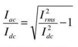
Ques.139. For a half-wave rectified sine wave the ripple factor is: (SSC-2014, M-Shift)
1.00
1.65
1.45
1.21
Answer.4. 1.21
Explanation:-
Ripple Factor (r): It is the ratio of root mean square (RMS) value of the AC component to the DC component in the output and is given by
For half-wave rectifier
Irms = Im/2
Idc = Im/π
For the half-wave rectifier, RMS Current is given as Im/2 and DC current Im/π which results in the ripple factor of 1.21