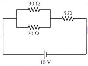
Ques.160. Power consumed in the given circuit is (SSC-2014, E-shift)
100 watts
5 watts
20 watts
40 watts
Answer.2. 5 watts
Explanation:-
30Ω and 20Ω resistor are connected in parallel
R’ = (30 x 20)/(30 + 20) = 12Ω
Now 12Ω and 8Ω resistance are connected in series
Req = 12 + 8 = 20Ω
Power consumed = (voltage)2/Resistance
=(10)2/20 = 5 watt
Ques.161. A 200 W, 200 V bulb and a 100 W, 200 V bulb are connected in series and the voltage of 400 V is applied across the series-connected bulbs, Under this condition (SSC-2014, E-shift)
100 W bulb will be brighter than 200 W bulb
200 W bulb will be brighter than 100 W bulb
Both the bulbs will have equal brightness
Both the bulbs will be darker than when they are connected across the rated voltage
Answer.1. 100 W bulb will be brighter than 200 W bulb
Explanation:-
To check the brightness of the lamp first we need to calculate the resistance of each lamp
For 200W, 200V bulb 1 the resistance is
P = V2/R or R = V2/P
R = (200)2/200 = 200Ω
For 100 W, 200 V bulb 2 the resistance is
R = (200)2/100 = 400Ω
Since the bulb are connected in series the total resistance will be
Req = 400 + 200 = 600Ω
I = V/Req = 400/600 = 2/3A
Since the bulbs are in series, the same amount of current flows through each of them.
Now note that the potential across each bulb, in this case, is not 400 volts. Instead, it is the voltage across the combination of bulbs.
The power at which each bulb is working is given by
P = V x I
If we substitute V = IR from Ohm’s law, we get
P = I2R
For bulb 1 power is
P = 200 x (2/3)2
= 800/9 W
For bulb 2 power is
P = 400 x (2/3)2
= 1600/9 W
Since the power of bulb 2 i.e 100 W bulb is more than the power of bulb1 200 W bulb. Hence the 100 W bulb will be brighter than the 200 W bulb.
Note:- Also It can be seen that the resistance of the 100W bulb is greater than the resistance of the 200 W bulb. Hence, the heat produced in the 100W bulb is more than produced in 200 W.Conclusion: 100W will glow brighter than the 200W bulb.
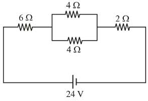
Ques.162. In the network shown, if one of the 4Ω resistances is disconnected, when the circuit is active, the current flowing now will (SSC-2014, E-shift)
Increased Very much
Decreased
Zero
Increase very slightly
Answer.2. Decreased
Explanation:-
If we do not remove the 4Ω resistance then the equivalent resistance is 10Ω
But if we remove one of the 4Ω resistance then the equivalent resistance become = 12Ω
Hence if any of the 4Ω resistance is disconnected then the total resistance is increased so current decreased.
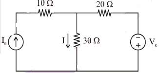
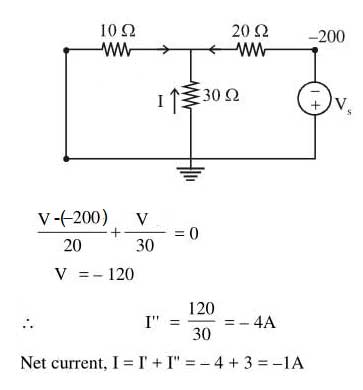
Ques.162. For the circuit shown in the figure, when Vs = 0, I = 3A, When Vs = 200 V, what will be the value of I? (SSC-2014, E-shift)
-4A
-1A
1A
7A
Answer.2. -1A
Explanation:-
Applying the current division rule when Is is short-circuited
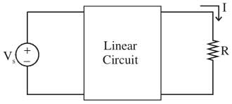
Ques.163. For the linear circuit shown in figure,
when R = ∞, V = 20 V;
when R = 0, I = 4 A;
when R = 5 Ω the current I is (SSC-2014, E-shift)
1 A
2 A
3 A
4 A
Answer.B. 2A
Explanation:-
From Ohm’s law
R = V/I
R’ = 20/4 = 5Ω
When R = 5Ω then current I is
I = V/R + R’
I = 20/5+5 = 2A
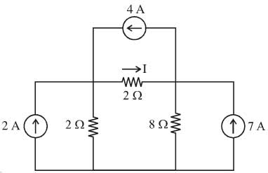
Ques.164. The current I in the circuit shown in the figure is (SSC-2014, E-shift)
-3.67 A
-1 A
4 A
6 A
Answer.2. -1 A
Explanation:-
Let the current passes from 2Ω resistance is i then
2i + 2(6 + i) – 8(3-i) = 0
4i + 12 +2i – 24 + 8i = 0
12i = 12
i = 1
Hence I = -i = -1A
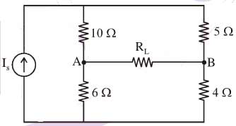
Ques.165. In the network shown in the figure, the value of R1 such that maximum possible power will be transferred to RL is (SSC-2014, E-shift)
5.76Ω
5.97 Ω
10.0 Ω
15.0 Ω
Answer.2. 5.97 Ω
Explanation:-
Disconnect the load resistance from the load terminals A and B
Thevenin’s equivalent resistance or resistance across the terminals AB is
From the maximum power transfer theorem, RL value must equal to the RTH to deliver the maximum power to the load.
Therefore, RL = RTH= 5.97 Ohm
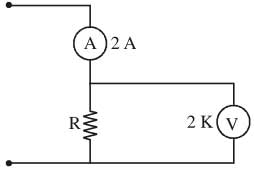
Ques.166. A resistance R is measured by the ammeter-voltmeter method. The voltmeter reading is 200 V and its internal resistance is 2 K. If the ammeter reading is found to be 2 A, then the value of R is (SSC-2014, E-shift)
105.3 Ω
100.0 Ω
95.3 Ω
90.3 Ω
Answer.1. 105.3Ω
Explanation:-
The Value of voltmeter across Rx is given as
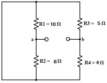
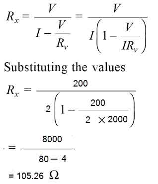
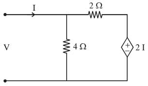
Ques.167. The circuit shown in the figure is equivalent to the load of (SSC-2014, E-shift)
4/3Ω
4 Ω
8/3Ω
2Ω
Answer.3. 8/3Ω
Explanation:-
Ques.168. A coil with a certain number of turns has a specified time constant. If the number of turns is doubled, its time constant would (SSC-2014, E-shift)
Remain unaffected
Become Double
Become four-fold
Get halved
Answer.3. Become four-fold
Explanation:-
The self-inductance of a solenoid is given as
L = μN2A/I = L1
where
N is the number of turns of the solenoid
A is the area of each turn of the coil
l is the length of the solenoid
and μ is the permeability constant
so, if the number of turns was to be doubled the self-inductance would be
L2 = u (2N)2A/l
or
L2 = 4L1
it would be quadrupled or increase fourfold.
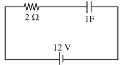
Ques.169. For the circuit shown in the figure, the voltage across the capacitor during the steady-state condition is (SSC-2014, E-shift)
0 V
4 V
6 V
12 V
Answer.4. 12 V
Explanation:-
In steady-state condition, the voltage across the capacitor equals the voltage of the charging source i.e 12 V.