Ques.51. A network has 10 nodes and 17 branches. then the total number of the independent loop will be (SSC 2016, Set-1)
9
6
7
8
Answer.4. 8
Explanation:-
The independent loop in a network
L = b – N +1
where
b total branches in the network
N total number of nodes
L = 17-10+1 = 8
Ques.52. If two resistances of 10 Ω and 10 Ω are connected in parallel the equivalent resistance is (SSC 2016, Set-1)
15Ω
5Ω
1Ω
100Ω
Answer.2. 5Ω
Explanation:-
When resistance is connected in parallel their equivalent resistance is
R = (R1 × R2)/(R1 + R2)
R = (10 × 10)/(10 + 10)
R = 5Ω
Ques.53. Which of the following capacitors of identical rating will have the smallest dimensions? (SSC 2016, Set-1)
Ceramic capacitor
Paper capacitor
Aluminum foil capacitor
Mica Capacitor
Answer.1. Ceramic capacitor
Explanation:-
Electrolytic Capacitors are generally used in DC power supply circuits due to their large capacitance and small size to help reduce the ripple voltage or for coupling and decoupling applications. Electrolytic’s generally come in two basic forms; Aluminium Electrolytic Capacitors and Tantalum Electrolytic Capacitors. The tantalum and electrolytic capacitors have ratings of 6, 10. 12. 15. 20. 25, 35, 50. 75, I00V and higher.
Paper capacitors: Paper capacitors use paper as the dielectric. They are made flat strips of metal foil plates separated by a dielectric, which is usually waxed paper. The paper capacitor has values in the picofarad and low microfarad, ranges. The voltage ratings are usually less than 6 V. Paper capacitors arc usually sealed with wax to prevent moisture problems.
The voltage rating of capacitors is very important. A typical set of values marked on a capacity might be “10 μF, 50 DCWV.” Such a capacitor h a capacitance of 10 μF and a “dc working voltage” of 50V. This means that a voltage in excess of 50 could damage the plates of the capacitors.
Ceramic capacitors: Ceramic capacitors make use of ceramic as the dielectric material. Basically, ceramic materials are fanned from titanium dioxide. Some of the dielectric materials used are barium titanate, magnesium titanic, and zirconium titanate.
Ceramic capacitors are produced as tubular, disk, and multilayer (monolithic) capacitors. Disk and tubular ones are inexpensive. Multilayer capacitors are rather expensive but they have small dimensions and low index.
The relative permittivity of mica ranges from 3–6(depending upon purity) and the relative permittivity of different types of ceramic ranges from 20–30. Clearly, ceramic capacitors have a higher capacitance. The maximum voltage rating of the ceramic capacitor is 10000 V, while the voltage rating of the mica capacitor is 4000 V.
Ques.54. Which of the following determines total power in a series circuit? (SSC 2016, Set-1)
Source voltage times the current
The total voltage applied to the circuit
Current flowing through a switch
Average of the wattage consumed by each resistor
Answer.1. Source voltage times the current
Explanation:-
The total power the in series circuit is given the current times of source voltage.
PTOTAL = Vs× Is
Vs: source voltage
Is: source current
Ques.55. The voltage applied across a ceramic dielectric produces an electrostatic field 100 times greater than in air. The dielectric constant, of the ceramic equals (SSC 2016, Set-1)
50
100
100/3
1/100
Answer.4. 1/100
Explanation:-
Since the voltage across a dielectric Capacitor.
V= 1/c ∫ i(t) dt
sicne C = ε A/d
C directly proportional to ε ( dielectric constant).
In turn, Voltage is Inversely proportional to the dielectric constant.
hence the dielectric constant, of the ceramic equals to 1/100.
Ques.57. The flow of electrons in the circuit constitutes (SSC 2016, Set-1)
E.M.F
Magnetic charge
Electric current
None of the above
Answer.3. Electric Current
Explanation:-
The concept of current and Electromotive force
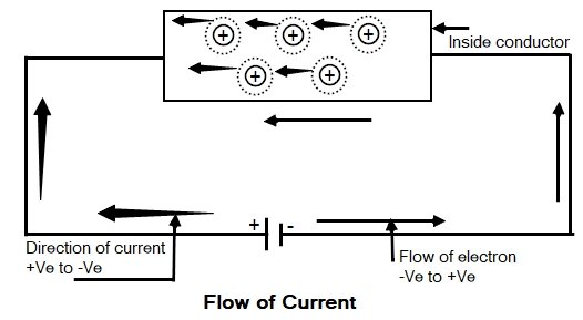
Consider a conductor which has large numbers of free electrons moving in the random direction. Now when we apply an external source to the conductor, then all free electrons drift along the conductor in a particular direction. The direction of the electrons will depend upon how the external source is applied to the conductor.
Hence the electrical source required to drift the free electron in a particular direction in a given conductor is called as an electrical Electromotive Force.
As we know that the free electrons are negatively charged, when the external source is applied (such as the cell) then free electrons get attracted by the positive of the cell connection. Therefore the electrons get aligned in the particular direction under the influence of an electromagnetic force.
An ion is an electrically charged particle produced by either removing electrons from a neutral atom to give a positive ion or adding electrons to a neutral atom to give a negative ion. When an ion is formed, the number of protons does not change.
When the free electron gets dragged towards positive from an atom it becomes the positively charged ion. Such positive ion drags a free electron from the next atom. This process repeats from atom to atom along the conductor. So there is the flow of electrons from negative to positive of the cell. This movement of electrons is called an electric current. The movement of electrons is always from negative to positive whereas the movement of current is assumed as positive to negative.
Relation between Charge and Current
The flow of electrons is called an electric current hence the current can be measured by the number of electrons passing through the material per second. In other words, the rate of flow of charge per unit time is called current. Current is measured in coulombs per second and one coulomb per second is called Ampere.
The relation between current and charge can be given as
I = Q/T Ampere
I = Average current flowing
Q = Total charge Transform
T = Time required for transfer of charge
Direction OF Current
In a source, the Direction of current is from lower potential to higher Potential while in an element the direction of current is from higher potential to lower potential.
Ques.58. In a parallel circuit operating with a source of 30 V AC, designed to carry a total current of 6 A, what happens to the protection device (fuse) when the resistance suddenly changes to 2Ω? (SSC 2016, Set-1)
There is no change
It closes
It opens
It shorts to ground
Answer.3. It opens
Explanation:-
When 30V AC source is carrying 6A the resistance of the path
ROLD= 30 /6 = 5Ω
New Resistance
RNEW = 2Ω
As resistance decreases the current in the circuit will increase and fuse gets open-circuited to protect the equipment from overcurrent.
Ques.59. Generally, an electrolytic capacitor is made to provide (SSC 2016, Set-1)
Fixed capacitance
Variable capacitance
Low capacitance
The large value of capacitance
Answer.4. The large value of capacitance
Explanation:-
Electrolytic Capacitors
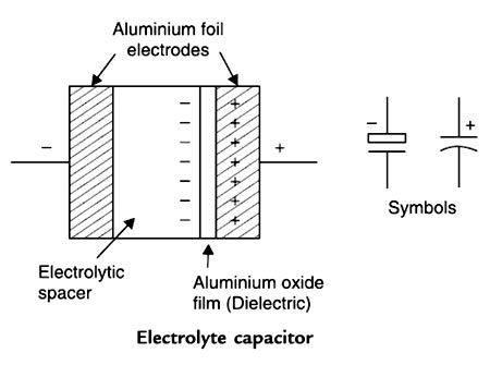
Electrolytic capacitors are generally used when very large capacitance values are required. Here, instead of using a very thin metallic film layer for one of the electrodes, a semi-liquid electrolyte solution in the form of jelly or paste is used which serves as the second electrode (usually the cathode).
The dielectric is a very thin layer of oxide which is grown electrochemically in production with the thickness of the film being Less than ten microns. This insulating layer is so thin that it is possible to make large value capacitors of a small size.
The majority of electrolytic types of capacitors are polarized, that is the voltage applied to the capacitor terminals must be of the correct polarity as an incorrect polarization will break down the insulating oxide layer and permanent damage may result.
Electrolytic capacitors are generally used in D.C. power supply circuits to help reduce the ripple voltage or for coupling and decoupling applications.
Electrolytic capacitors are most commonly based on either aluminum or tantalum electrode materials.
The metal electrode materials are processed so that they have a very high surface area, which results in high capacitance. In the case of aluminum electrolytic capacitors, the positive electrode (anode in a capacitor) starts as a thin foil that has been etched to create a large number of tunnels.
The tantalum and electrolytic capacitors have ratings of 6, 10. 12. 15. 20. 25, 35, 50. 75, I00V and higher.
Ques.60. Calculate the length of the wire required for an electric radiator to dissipate 1 kW when connected to a 230 V supply, if the coils of the radiator are made of wire 0.5 mm in diameter having the resistivity of 60 μΩ.cm (SSC 2016, Set-1)
400 cm
753 cm
1732 cm
1456 cm
Answer.3. 1732 cm
Explanation:-
Given Power P = 1 kW Voltage V = 230 V Diameter d = 0.5 mm Resistivity ρ = 60 μΩ.cm Area a = π/4.d2
As we know that power P is given by
P = V2 ⁄ R
R = 2302 ⁄ 1 × 10³
R = 52.9 Ω
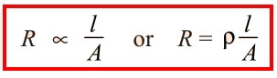
For any given material at a certain given temperature, the resistance is given as
where ρ is a constant and known as its specific resistance or resistivity.