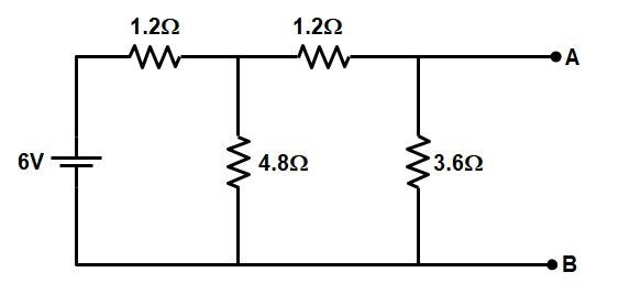
Ques.71. The resistance across terminals ‘a’ and ‘b’ in the circuit shown will be __________.
10.8 Ω
2.45Ω
6 Ω
1.35 Ω
Answer.4. 1.35 Ω
Explanation:-
Applying Thevenin’s theorem in the given question
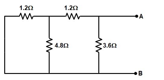
Thevenin’s resistance can be found by replacing 6 V source with a short-circuit.
To find the Thevenin’s resistance first we have to reduce the circuit.
⇒The resistance 1.2 Ω and 4.8 Ω are in parallel
= (1.2 × 4.8) ⁄ (1.2 + 4.8) = 0.96Ω
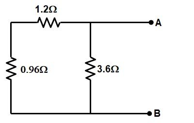
⇒ Now the Resistance 0.96 Ω and 1.2 Ω are in series
= 0.96 + 1.2 = 2.16Ω
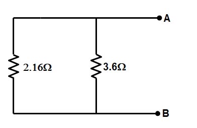
⇒ Finally, the Resistance 2.16 Ω and 3.6 Ω are in parallel
= (2.16 × 3.6) ⁄ (2.16 + 3.6) = 1.35Ω
Rab = 1.35Ω
Ques.72. The electric flux and field intensity inside a conducting sphere is (SSC 2016, Set-2)
Maximum
Uniform
Zero
Minimum
Answer.3. Zero
Explanation:-
Why is the electric field inside a conductor zero?
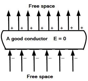
Let a plane conductor that has no initial charge be placed in a uniform static electric field in free space, as shown in Fig.
Every free electron of the conductor will experience an electric force equal to eE, where e is the value of the charge of an electron and E is the intensity of the applied field.
The electrons will move in the opposite direction of the applied field until they reach the bottom surface of the conductor and then get distributed on the conductor surface in the form of a surface charge.
The positive charges, which are generated in the conductor after the migration of the electrons, move to the top surface and get distributed over a thin layer.
The charges cannot move beyond the conducting surfaces because the medium surrounding it is an insulator.
The surface charges produce an induced electric field within the conductor. As the induced field is directed from the top surface having a positive charge towards the bottom surface, it is opposite to the applied field.
When the magnitude of the induced field becomes equal to that of the applied field, the net field intensity inside the conductor will become zero That is the Electric field due to the charges inside the conductor is directed opposite to the electric field outside due to which the field inside the conductor originated.
Remember: The charges move in a conductor so as to kill the external field
Consequently, no further movement of charges will take place. That is, the static condition will be reached after a brief transient period during which charges move to the surfaces. External field lines terminate on the bottom surface and emerge from the top surface, as shown in the figure.
Since field intensity inside a good conductor is zero, the potential gradient, which is numerically equal to the field intensity, is also zero. Accordingly, the potential has the same value everywhere inside a good conductor.
Ques.73. What happens to current flow in a capacitance circuit when the DC voltage across the capacitor is approximately equal to the source voltage? (SSC 2016, Set-2)
Current flow is optimized
Little current flows
Current flow is maximum at the source
Current flow is maximum at the capacitor
Answer.2. Little current flows
Explanation:-
A capacitor is nothing but 2 metal plates separated by an insulator. The insulator can be anything like paper, air, rubber, etc.
When a capacitor is connected to a voltage source, positive charges from the positive terminal of the voltage source and negative charges(electrons) from the negative terminal of the voltage source, travel and GET ACCOMMODATED ON BOTH THE PLATES OF THE CAPACITOR.
Once the capacitor gets fully charged it will now act as the insulator and it doesn’t allow current to pass through it.
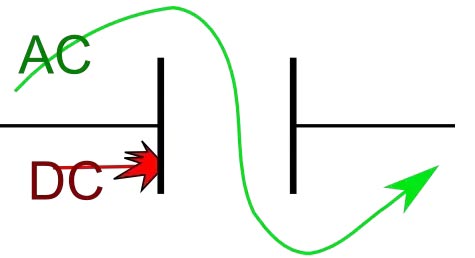
Now as we know that the voltage value of DC remains constant for all the time the power supply is ON. Hence capacitor gets charged to its total limit and thus doesn’t allow any current to flow hence DC BLOCKED.
Talking about AC it is the time-varying Voltage i.e the polarity of AC changes from time T1 to T2, therefore, at time T1, the capacitor gets charged such that the positive charges are accommodated on the left plate.
After time T1, the polarity changes (because the voltage source is AC) and now at the start of T2, voltage source V will attract the negative and positive charges from the respective plates to its terminals and current will flow in another direction. And because the capacitor is losing its charges – the Capacitor is getting discharged.
Just like resistors, capacitors also offer some form of resistance against the flow of current through the circuit, but with capacitors, in AC circuits this AC resistance is known as Reactance.
Capacitive Reactance = 1/2πfC
As the frequency is increasing the capacitive reactance is slowly reaching zero value. In AC circuit we suppose that the frequency value is sufficiently high to make capacitive reactance zero or the capacitor behaves equivalent to the short circuit.
Ques.74. Branch circuit must not feed more than __________ points (SSC 2016, Set-2)
5
10
12
8
Answer.2. 10
Explanation:-
The branch Circuit must not feed more than 10 points.
Ques.75. The shunt element of the prototype high filter is (SSC 2016, Set-2)
Resistive
Inductive
Capacitive
Combination of inductance and capacitance
Answer.2. Inductive
Explanation:-
A filter is a circuit that is designed to pass a specified band of frequencies while attenuating all the signals outside that band. It is a frequency selective circuit.
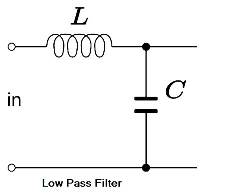
Low Pass Filter:- The low pass filter passes the low-frequency signal from input to output while it blocks high-frequency signals from the input. A low pass filter (even or odd orders based on a ladder network consists of shunt capacitors and series inductors that interconnect these shunt capacitors. No inductor is grounded. The load impedance/resistance is always grounded. For an even order low pass filter, the least reactive element is always an inductor, whereas, for an odd order filter, the last reactive element is always a capacitor.
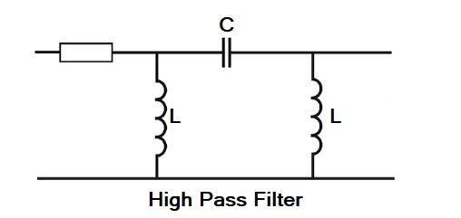
High Pass Filter:- In high pass filter, the filter rejects the frequencies which are less than cut-off frequencies ωo and it allows to pass the frequencies which are greater than ωo. The topology of a ladder network-based high pass filter is complementary to that of a ladder network-based low pass filter. Now all inductors are shunted, and series capacitors interconnect these shunt inductors. The load impedance/resistance is always grounded.
Band Pass Filter:- A band-pass filter is one designed to pass signals with frequencies between two specified cut-off frequencies. A ladder network-based bandpass filter consists of alternating pairs of series and parallels connected capacitors and inductors. Each pair of the parallel-connected capacitor and inductor id grounded. Each series-connected pair of capacitor and inductor interconnects two pairs of parallel-connected capacitors and inductors.
Ques.76. Static electricity is produced by (SSC 2016, Set-2)
Chemical Reaction
Friction
Induction
Both friction and Induction
Answer.2. Friction
Explanation:-
Static Electricity
The oldest method of moving electrons is by static electricity. Static electricity produces a flow of electrons by permanently displacing an electron from an atom. The main characteristic of static electricity is that a prolonged or steady flow of current is not possible. As soon as the charges between the two substances are equalized (balanced, electron flow stops.
Static electricity is an electric charge that does not flow in an electric current from a battery or along an electric wire to light a bulb or some other electric tool. Static electricity is a charge that stays in one place.
Static electricity can be produced by friction when two materials are rubbed together. During the process of rubbing, electrons can be rubbed off from the atoms of one material and onto the atoms of another material. The materials used to create a static charge must be electrical insulators, materials that do not conduct electricity. If they were conductors, like copper, aluminum, or water, the charge would just flow away. Some common insulators that create static charges are rubber, cloth, hair, and plastic.
Electricity Through Chemical Means
Electricity can also be produced by the movement of electrons due to chemical means. A battery produces an electron flow by a chemical reaction that causes a transfer of electrons between two electrodes. An electrode is a solid conductor through which an electric current can pass.
One electrode collects electrons and one gives away electrons. The dry cell battery uses two electrodes made of two dissimilar metals inserted in a pastelike electrolyte. Electricity is produced when a chemical reaction occurs in the electrolyte between the electrodes, causing an electron flow.
Electricity Through Magnetism or Induction
The magnetic or induction method of producing electron flow uses a conductor to cut through a magnetic field, which causes a displacement of electrons. The alternator, generator, and transformer are the best examples of the magnetic method. The magnetic method is used to supply electricity to consumers.
The flow of electrons in a circuit produces magnetism, which is used to cause movement, or thermal energy, which in turn is used to cause heat. A magnetic field is created around a conductor—an apparatus for electrons to flow through—when there is a flow of electrons in the conductor. The flow of electrons through a conductor with resistance will cause heat, such as in an electric heater.
The heating, cooling, and refrigeration industry uses magnetism to close relays and valves and to operate motors by using coils of wire to increase the strength of the magnetic field.
Ques.77. Which set of rules is to be verified on the completion of wiring on any new installation? (SSC 2016, Set-2)
Indian Electricity rules, 1950
Indian Electricity rules, 1956
Indian Electricity rules, 1960
None of these
Answer.2. Indian Electricity rules, 1956
Explanation:-
The Indian Electricity Rules, 1956 was made under section 37 of the Indian Electricity Act, 1910 (now repealed after enactment of The Electricity Act, 2003, but these rules themselves has been allowed to be in force till rules under section 53 of new Act are made). These Rules mainly deal with:-
i. Appointment of inspectors & their duties. ii. Licensing provisions. iii. General safety requirements. iv. Conditions relating to supply and use of energy. v. Electric supply lines and systems for LV & MV. vi. Electric supply lines and systems for HV & EHV. vii. Overhead lines, underground cables and generating stations. viii. Electric traction. ix. Precautions in mines & oil fields.
Ques.78. Which of the following is an active element of a circuit? (SSC 2016, Set-2)
Resistance
Inductance
Capacitance
Ideal current source
Answer.4. Ideal current source
Explanation:-
The active elements generate energy or which gives power to the circuit elements. Like the voltage source and the current source, Batteries, generators, operational amplifiers, etc are active elements.
Ques.79. Two condensers of capacity 2F and 3F are connected in series, the third condenser of 1F is connected in parallel to them, the resultant capacity in Farad (F) will be (SSC 2016, Set-2)
6F
5/11 F
5/6 F
11/5 F
Answer.4. 11/5 F
Explanation:-
Capacitor 2F and 3F are connected in series, therefore, the resultant capacitance
C = (2 × 3)/(2 + 3) = 1.2 F
Now Capacitor 1.2 F and 1 F are connected in parallel hence
C = 1.2 F + 1F = 2.2 F = 11/5 F
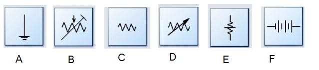
Ques.80. In the figures given below, which figure is the electrical symbol for a source of energy? (SSC 2016, Set-2)
Figure A
Figure C
Figure F
Figure E
Answer.3. Figure F
Explanation:-
Figure F is the symbol of the battery and the battery is the source of energy.