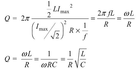
In a practical circuit R is essentially resistance of the coil since practical capacitors have very low loss in comparison to practical inductor. Hence Q is a measure of the energy storage property (LI2) in relation to the energy dissipation property (I2R) of a coil or a circuit. The Q is, therefore, defined as
In electric circuit energy is stored in the form of electromagnetic field in the inductance where as in electrostatic form of energy across a capacitance.
Maximum energy stored = Electromagnetic energy in Inductor or Electrostatic Energy in Capacitor
[latex]=\dfrac{1}{2}L{{\mathop{\rm I}\nolimits} _{\max }}^2{\text{ or }}\dfrac{1}{2}C{V_{\max }}^2[/latex]
We know that average power P
P = I2R = Where I = Im ⁄ √2 = 1⁄2 I2mR
Energy dissipated per cycle = P ⁄ f
Therefore,
Where ω = Resonance frequency = 1/√LC
Thus, Q is inversely proportional to R. Hence, for series RLC circuit, a high value of quality factor implies low losses and a low value of Q implies high losses.
Also, the quality factor for a circuit is defined as
Therefore, a circuit will be highly selective if it has a high value of Q. For a series RLC circuit, a high value of the quality factor implies a narrow resonant peak and a low value of Q implies broad resonant peak. The variations of magnitude and phase angle of current in an RLC series circuit for different values of quality factor (Q).
Ques.83. Which of the following represent the relation between the peak value and the RMS value of voltage for a sine wave? (SSC 2018 S-3)
Vrms = 1.414Vpeak
Vrms = 0.637Vpeak
Vrms = 0.424Vpeak
Vrms = 0.707Vpeak
Answer.4. Vrms = 0.707Vpeak
Explanation
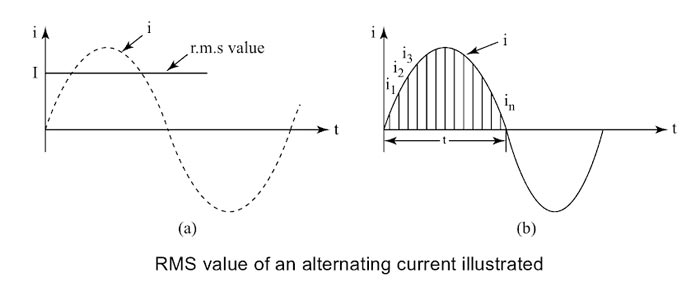
The effective or r.m.s. value of alternating current is that steady current (d.c.) which when flowing through a given resistance for a given time produces the same amount of heat as produced by the alternating current when flowing through the same resistance at the same time. It is also called virtual value of a.c. and is represented by Irms or Ieff or Iv.
For example, when we say that r.m.s. or effective value of an alternating current is 5A, it means that the alternating current will do work (or produce heat) at the same rate as 5A direct current under similar conditions.
To determine r.m.s. value of a sinusoidal alternating current, we have to first square it, then take its mean over one cycle or half cycle and then take the square root (note that r.m.s. value is calculated by making reverse operation, that is, the first square, then take mean and then take square root).
Square of current i = Im sinθ = I2m sin2θ
Its mean over one cycle is calculated by integrating it from 0 to 2π and dividing by the time period of 2π.
Hence the r.m.s. value or effective value or virtual value of alternating current is 0.707 times the peak value of alternating current for the half-cycle as well as for full cycle.
Ques.84. What will be the frequency (in Hz) of a sinusoidal waveform, when the time period of the wave is 25 ms? (SSC 2018 S-3)
40
50
60
80
Answer.40
Explanation
Frequency is inversely proportional to the time period
F = 1/T = 1/(25 × 10−3)
F = 40 Hz
Ques.85. Determine the average value of an alternating current (in A) when the peak value of the current is 10A. (SSC 2018 S-3)
14.14
10.63
6.37
4.36
Answer.3. 6.37
Explanation
The average value of alternating current (sinusoidal) is zero over one cycle. It is because of the positive area exactly cancels the negative area. However, the half-cycle average value is not zero.
Therefore if an average value of alternating current and voltage is asked, it is understood for the half cycle.
I = Imsinωt
And the average value of an alternating current is given by
Iavg = 2Im ⁄ π = 0.637Im
Where
Im = peak value of alternating current = 10A
∴ Iavg = 0.637 × 10 = 6.37A
Iavg = 6.37A
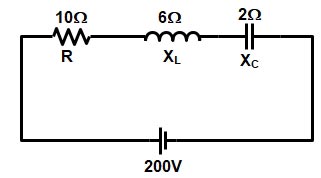
Ques.86. Determine the total impedance (in ohms) of a series RLC circuit having a resistance of 10 Ohms, capacitive reactance of 2 ohms and the inductive reactance of 6 ohms, connected in a series across a 200 V, 50 Hz supply. (SSC 2018 S-3)
8.64
10.77
12.21
14.65
Answer.2. 10.77
Explanation
In RLC series circuit the total impedance of the series LCR circuit is given as
Z2 = R2 + (XL – XC)2
where
R = Resistance = 10Ω
XL is inductive reactance = 6Ω
and XC is capacitive reactance = 2Ω
Z2 = 102 + (6 − 2)2
Z2 = 116
Z = 10.77Ω
Ques.87. Determine the value of the phase current (in A) for a balanced delta connected system, when the value of the line current is 8.7 A. (SSC 2018 S-3)
8
6
7
5
Answer.4. 5
Explanation
In a delta connected system, the phase current is 1/√3 times the line current.and the phase voltage is equal to the line voltage of the system.
IPH = Line/√3
IPH = 8.7/√3 = 5.02 A
IPH = 5.02 A
Ques.88. What will be the value of inductance (in mH) connected in parallel with a capacitance of 4F in a series RLC circuit having the quality factor of 2, when the resonant frequency is 6 rad/sec?
2
3
5
7
Answer.4. 7
Explanation
As explained in question no 32 the quality of the RLC circuit is given as
Q = ωoL ⁄ R ———— (1)
or
Q = 1 ⁄ ωoC.R ———–(2)
Now the given quantities are
Quality factor Q = 2
Resonance Frequency = ωo = 6 rad/Sec
Capacitance C = 4 F
Resistance R =?
Inductance L = ?
Now from equation Number 2, we can find the value of resistance
Q = 1 ⁄ ωoC.R
2 = 1 ⁄ 6 ×4 × R
R = 1 ⁄ 48 Ω
Now again To find the value of an inductance we will use equation number 2
Q = ωoL ⁄ R
2 = 6 × L ⁄ 1 ⁄ 48
L = 0.0069 ≅ 0.007
L = 7mH
Ques.89. What will be the value of average power (in W), if a sinusoidal voltage applied across a series RC circuit is 20 sinωt V and the current flowing in the circuit is 10sin (ωt + 60) A?
50
60
80
100
Answer.1. 50
Explanation
Let the expression be as follows:-
I(t) = Im sin(ωt ± φ)
Where φ represent the concerned phase-shift
Im = Maximum value of the current = 10 A or IRMS = Im/√2 = 10/√2
φ = 60°
Similarly
V(t) = Vm sin(ωt ± φ)
Vm = 20 V or VRMS = 20/√2
Average power consumed is
PAVG = VRMS. IRMS. Cosφ
PAVG = (20/√2) × (10/√2) × Cos60°
PAVG = 200/4 = 50 watt
PAVG = 50 watts
Ques.90. Determine the total power (in kW) consumed in the 3-Phase delta connected system supplied by line voltage of 230 V, if the value of the phase current is 30 A and the current lags the voltage by 30 degrees.