Ques.31. The instantaneous power of a 1-phase series circuit supplying R-L load from a sinusoidal voltage source has in each cycle (SSC-2013)
Negative twice, zero four times
Zero twice, negative once
Negative four times, zero twice
Negative twice, zero once
Answer.1. Negative twice, zero four times
Explanation:
Instantaneous power is the power of the object at any instant of time, in general, it is defined as p(t) = v(t) x i(t)
In a single-phase ac circuit, the instantaneous power to a load is of pulsating nature. Even at unity power factor, the instantaneous power is always less than unity
For a sinusoidal signal, the voltage swings through zero volts twice a cycle, so the instantaneous power is zero two times per cycle.
If the load has both resistance and reactance, then the current, and voltage swings through zero twice a cycle, with different phase angle and thus the instantaneous power will swing through zero 4 times a cycle.
Instantaneous power is positive for one part of the cycle and negative for another part of the cycle if there is both resistance and reactance in the circuit. then there will be one negative for voltage and one negative for current thus instantaneous power will have two negative per cycle for single-phase R-L series circuit.
Ques.32. In a series R-L-C circuit, the “Q-factor” is given by (SSC-2013)
1/R√L/C
R√L/C
1/R√C/L
R√C/L
Answer.1. 1/R√L/C
Explanation:
Q factor is a parameter that describes the resonance behavior of an underdamped harmonic oscillator (resonator).
In an ideal series RLC circuit, and in a tuned radio frequency receiver (TRF) the Q factor is: 1/R√L/C
The larger the series resistance, the lower the Q factor.
Ques.33. In an ac circuit, V = (200 + j40) V and I = (30 – j 10) A. The active and reactive power of the circuit are respectively (SSC-2013)
6400 W, 800 VAR capacitive
6400 W, 800 VAR inductive
5600 W, 3200 VAR capacitive
6400 W, 3200 VAR inductive
Answer.2. 6400 W, 800 VAR capacitive
Explanation:
Active power = 200 x 30 + 40 x10 =6400 W
Reactive Power = 200 x 10 – 40 x 30 = 800 VAR
Ques.34. Application of Norton’s theorem in a circuit results in (SSC-2013)
A current source and impedance in parallel
A voltage source and impedance in series
An ideal voltage source
An ideal current source
Answer.1. A current source and impedance in parallel
Explanation:
Norton’s theorem illustrates that a network consists of several voltage sources, current sources and resistors with two terminals, which is electrically equivalent to an ideal current source ” INO” and a single parallel resistor, RNO
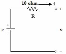
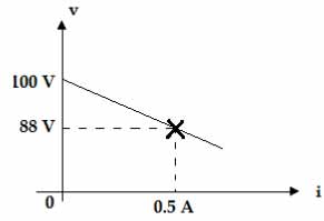
Ques.35. The voltage (v) vs. current (i) curve of the circuit is shown below: (SSC-2013)
24 Ω
4 Ω
10 Ω
14 Ω
Answer 4. 14 Ω
From the circuit diagram
e = V – 10i
r = e/i
= V/i -10
On differentiating
dr = dv/di -10
= 12/0.5 – 10 = 14 Ω
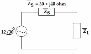
Ques.36. Value of the load impedance ZL for which the load consumes maximum power is (SSC-2013)
50 Ω at a power factor of 0.6 lead
50 Ω at a power factor of 0.6 lag
30 Ω at a power factor of unity
None of the above
Answer.1. 50 Ω at a power factor of 0.6 lead
Explanation:
For maximum power transfer
ZL = Zs* = 30 – j40
Apparent power
Zs2 = 302 + 402
Zs = 50 Ω
Power factor = Real power/ Apparent power
CosΦ = 30/50 = 0.6 leading
A leading power factor signifies that the load is capacitive, as the load “supplies” reactive power, and therefore the reactive component Q is negative as reactive power is being supplied to the circuit.
Ques.37. Three equal impedances are first connected in delta across a 3-phase balanced supply. If the same impedances are connected in star across the same supply (SSC-2013)
Phase currents will be 1/3 rd of the previous value
Line currents will be 1/3 rd of the previous value
Power consumed will be 1/3 rd of the previous value
Power consumed will be 3 times the previous value
Answer.3. Power consumed will be 1/3 rd of the previous value
Explanation:
Let us suppose Vs be the supply voltage per phase.
So the line voltage of the supply will be 3Vs.
Now assume any type of load; for simplicity, let’s assume it a resistive load which is R per phase
For Delta connected load:
Calculation of per phase power; PD= I2R
Where I is load current (per phase) And,
I = √3Vs/R {as line voltage of the supply is directly applied to the phase of the delta load}
So,
Pd = (√3Vs/R )2R = 3Vs2/R watts per phase.
For 3 phases:
P3D = 3Pd = 3*3Vs2/R = 9Vs2/R watts.
Now for Star connected load:
PS = I2R = (Vs/R)2R = Vs2/R watts
For 3 phases: P3S = 3PS = 3 Vs2/R watts
Conclusion:
P3S / P3D = 3Vs2/R / 9Vs2/R = 1/3
i.e The power ratio between Star to Delta is 1:3
Ques.38. The average value of the voltage wave V= 110 + 175 sin (314 t – 180°) volts is (SSC-2013)
110 V
175 V
165.57 V
206.7 V
Answer.1. 110 V
Explanation:
The average value of the second term is zero therefore answer is 110 V.
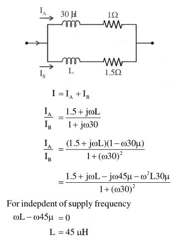
Ques.39. Current from an ac source bifurcates into two branches A and B in parallel. Branch A is an inductor with 30 μH inductance and 1 Ω resistance. Branch B is another inductor with inductance L and 1.5 Ω resistance. For the ratio of currents in the branches to be independent of supply frequency, the value of L should be (SSC-2013)
30.5 μH
20 μH
45 μH
29.5 μH
Answer.3. 45 μH
Explanation:
The diagram of the above question can be constructed as
Ques.40. Three inductors each of 60 mH are connected in delta. The value of inductance of each arm of the equivalent star connection is (SSC-2013)