
Ques.11. Which of the given losses are directly proportional to the square of speed? (SSC-2018 Set-3)
- Windage Loss
- Eddy current Loss
- Both Windage and eddy current loss
- Hysteresis loss and brush loss
Answer.3. Both Windage and eddy current loss Explanation:- There are three types of losses in a DC machine Eddy’s current Loss. Eddy current losses occur because the iron core of the armature is a conductor revolving in a magnetic field. This sets up an emf across portions of the core, causing currents to flow within the core. These currents heat the core and, if they become excessive, may damage the windings. As in the cases of induction and synchronous machines, the number of poles of a d.c. the machine does not bear a relation with speed and frequency. On the other hand, the frequency of flux reversal in the armature is given by the relation, f = P. Nr where Nr is the armature speed in r.p.s. That is, for any constant speed Nr, f is directly proportional to the number of poles. Thus, with a large number of poles, a large frequency of flux reversal may result in large iron losses in armatures For the armature teeth, such losses may be excessive since teeth are generally worked at a density near saturation. Generally, f = 25 Hz. is satisfactory, though, for smaller machines, f can be as high as 50 Hz. Eddy current losses in the DC Machine are given by Eddy current losses = Ke × Bm2 × f2 × V ×t2 Where The frequency of magnetic field density in a stator is 50 Hz (frequency of power supply), while in a rotor the frequency is much higher and depends on the motor speed. Since the eddy current losses depend on the square of the frequency, hence Eddy current loss in the armature teeth and in the armature core is proportional to the square of the speed and to the square of the air-gap flux density. Note:- Eddy current losses also depends upon the square of the thickness of the lamination The friction losses occur in bearings and commutators. The value of bearing friction losses depends upon the pressure in bearing, the peripheral speed of the shaft at bearing and the coefficient of friction between the bearing and the shaft. The windage losses produced by rotation depend upon the peripheral speed of the rotor, the rotor diameter, the core length and the construction of machines. (3) Friction losses consist of bearing, brush and windage losses. The brush contact losses are electrical and are located a the brush-commutator interface. They are proportional to armature current. The brush friction and bearing friction losses are generally proportional to speed. Circulating currents of air set up as the armature rotate result in a loss known as windage loss, but these can vary widely and are very much affected by the presence of a cooling fan attached to the armature the air volume, fan pressure, and the fan efficiency. The windage loss includes the Wind friction loss i.e power required to circulate air through the machine and ventilating ducts and is approximately proportional to the square of speed.
Ke = Eddy current constant
t = thickness of the core
V = Volume of material
Bm = Maximum flux density
f = frequency
Ques.12. Armature reaction effect is more in (SSC-2018 Set-3)
- Field weakening Method
- Armature resistance control
- Same in both method
- All of the above
Answer.1. Field weakening Method Explanation:- For the operation of any d.c. machine, the presence of magnetic flux is essential. Whenever current flows through a field coil, it produces a flux which is called as field flux or the main flux. Now suppose the d.c. the machine is functioning as a generator if a load is connected to the DC generator, the armature, the armature current begins flowing in the armature winding and the armature conductor (Ia.Na). This armature current produces a magnetic field of its own which distorts the original magnetic field produced by the field winding. This distortion of the main field (series and shunt field) as the load on the DC machine is increased is called as the armature reaction. In general, speed control of DC motor drives can be accomplished by two methods: armature voltage control and flux-weakening control. The speed control of DC motors by armature voltage control is used for speeds below normal, while for speeds above normal field weakening method is used as N ∝ Eb/ φ. When the field voltage of the DC motor is weakened while the armature voltage is fixed, the motor back EMF decreases. Because of low armature resistance, the armature current will increase by an amount much larger than the decrease in the field. Through the field weakening control, the operating speed can be increased, but as we know that in the case of DC motor T ∝ φf. Ia, to get the same torque as the torque without the field weakening the armature current should be increased by the amount by which the flux reduced. Also, to increased armature current results in increased copper losses. The maximum armature current usually limited due to the thermal limit of the machine itself or due to the other parts of the drive system. Hence, if the speed is increased by the field weakening, then the available maximum torque at the increased speed is reduced proportionally to the reduced field flux. Moreover, in the field flux weakening operation, the armature reaction is relatively large due to an increase in the armature current and the commutation problem may occur. Because of the higher operating speed by the field weakening control, the mechanic problems in the commutator and the brush of the machine may also occur. Hence, the minimum flux level for the field flux weakening control is usually limited down to a certain value—for example, one-third of the rated value.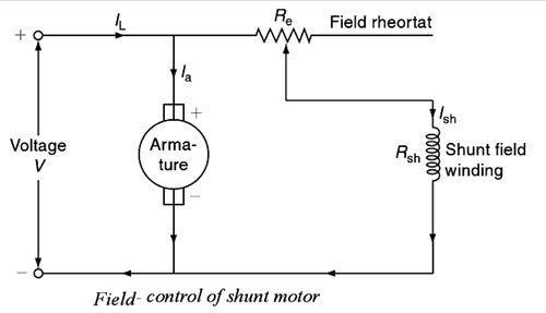
Ques.13. The aiding ampere-turns of the series field automatically (SSC-2018 Set-3)
- Decrease with Load
- Increase with Load
- Equal to the load
- None of these
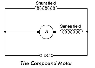
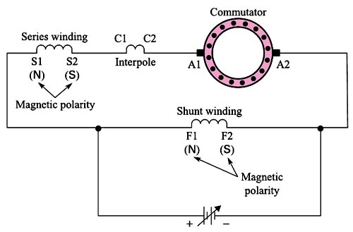
Answer.2. Increase with Load Explanation:- Generally, there are 4 types of DC Motor Note:- Firstly we should Know the Ampere Turn is the unit of Magnetomotive force The DC compound motor is a combination of the series motor and the shunt motor. It has a series field winding that is connected in series with the armature and a shunt field that is in parallel with the armature. The combination of series and shunt winding allows the motor to have the torque characteristics of the series motor and the regulated speed characteristics of the shunt motor. If the series field MMF (Ampere-Turns) aids the shunt field MMF (Ampere Turns), the generator is said to be cumulative compounded. When the series field MMF opposes the shunt field MMF, the generator is said to be differentially compounded. Cumulative Compound Motor The causes of voltage drop in the terminal voltage from no-load to full-load in a shunt generator can be partial/fully/overcompensated by the use of an aiding series field (cumulative compound), which can be connected in a long or short-shunt. The aiding ampere-turns of the series field automatically increase with the load, compensating the armature voltage drop. In a level-compound generator, full-load voltage equals no-load voltage. Steady-state volt-ampere (V-I) characteristics of a The series and shunt windings of the cumulative compound motor are connected so that their magnetic fields have the same polarity, as shown in Figure. in this configuration, the magnetic fields of both windings are additive (cumulative). The series field has the most impact on the operation when the motor is first turned on. Since the armature is not turning and producing a back EMF, a large amount of current flows through the series coil, and a strong field is established immediately. This provides a high torque when starting, or when the load demand suddenly increases. Suppose that the cumulative compound motor is operating in an under-load condition when the physical load is increased. The motor slows down, the back EMF reduces, and the armature and series field current increases. However, since the armature is cutting the shunt field that has a constant strength, the amount that the back EMF; weakens is limited. Enough current flows through the armature to create the necessary magnetic interaction (between the armature, series, and shunt coils) to match the torque demand of the increased load, the motor speed stops changing. The change in speed is more than that of a shunt motor but less than a series motor. The speed regulation of a cumulative compound motor is about 25 percent. If the cumulative compound motor encounters a no-load condition, the armature will speed up. However, it does not have the run-away characteristics of the series motor because a large enough Back EMF is developed as the armature cuts through the series and shunt coil fields. When the armature current decreases to a certain level, the torque reduces so that it can no longer accelerate the motor, and the speed stabilizes. IN Short:- In Cumulative compound Motor, the total MMF increases with the increase of the load. In this type, there is one component of the field flux that is constant while the other is proportional to the armature current. When the motor runs at no-load, the armature current I in the series winding is low and the MMF of the series field is negligible. However, the shunt field is fully excited by the current, and so the motor behaves like a shunt machine: it does not tend to run away at no-load. Hence at light loads, it behaves very close to the shunt motor characteristic as the effect of the series field flux will be very small. As the load increases, the MMF of the series field increases but the MMF of the shunt field remains constant. The total MMF (and the resulting flux per pole) is, therefore, greater under load than at no-load. The motor speed falls with increasing load and the speed drop from no-load to full-load is generally between 10 percent and 30 percent. Hence The cumulating e compound motor develops a high torque to match an increase in the torque load as does a series motor. This type of connection combines the best features of both the series type (represented by high starting torque) and the shunt type (represented by no over-speed occurrence at no-load).
Ques.14. A Shunt motor running at 1000 rpm generated emf of 100 V. If the speed increase to 1200 rpm, the generated emf is (SSC-2018 Set-3)
- 140 V
- 120 V
- 240 V
- 360 V
Answer.2. 120 V Explanation:- The back EMF of DC Motor is given as Eb = PφZN ⁄ 60A Where P – Number of poles of the machine ϕ – Flux per pole in Weber. Z – Total number of armature conductors. N – Speed of armature in revolution per minute (r.p.m). A – Number of parallel paths in the armature winding. So from the above result, we can say that in DC motor the back EMF is directly proportional to the speed and flux. E ∝ Nφ Let initially the EMF generated by the Motor be Eb1 and the speed be N1 Now the change in speed is N2 and change in flux be Eb2 Eb1 = 100 V N1 = 1000 RPM Eb2 =? N2 = 1200 RPM Eb1 ⁄ Eb2 = N1 ⁄ N2 100 ⁄ Eb2 = 1000 ⁄ 1200 Eb2 = 120 V
Ques.15. Which type of load is offered by cranes and hoists? (SSC-2018 Set-3)
- Gradually varying load
- Non-reversing, no-load start
- Reversing, light start
- Reversing, Heavy start
Answer.4. Reversing, Heavy start Explanation:- The load offered by cranes and Hoist is reversing and it also used to carry the heavy load. Let us explain in detail Hoists Hoists are a means of transporting materials or passengers vertically by means of a moving level platform. Materials hoist come in basically two forms i.e static and mobile models. The hoist can be driven by petrol, diesel, or electric motor and can be of a cantilever or enclosed variety. Crane A crane is the type of machine mainly used for handling heavy loads in different industry branches: metallurgy, paper, and cement industry. By the construction, cranes are divided into the overhead and gantry cranes Torque and power requirements for crane and Hoist drives Speed control is an essential feature in crane drives. It is required for allowing soft starting and stopping of the travel motions for enabling its correct positioning of the load. For the lifting drive the speed control in a wide speed range, from zero to nominal values, is required. Because of the precision when raising and lowering load, the possibility of working at a very low speed and hold a load at the standstill is required, without using the mechanical brakes. Crane and Hoist are to be started and stopped for frequent starting, stopping and reversing operation. They require a high starting of three times the normal full-load torque. It is therefore recommended, that a high-slip induction motor is to be used for the drive. Also, DC series motor is recommended, as it provides high starting torques Among the d.c. motors, the series motors, and cumulative compound motors are most preferred for crane operations. The motors have good starting torque, high torque capacity at light loads, the simple arrangement of braking, electric braking at low speeds is possible. The only disadvantage is that the motors are less stable while the regenerative braking. Plugging in D.C motor is not only used to bring a motor to stop but is also used in drives where quick reversal of drive is required, such as, in cranes and Hoist. In a crane, plugging is done with the help of master controllers. This is done by moving the handle from a full-speed forward position to full-speed. reverse position or vice-versa. Ward Leonard system is commonly employed for elevators, hoists, and main drive in steel mills, as this method can give unlimited speed control in either direction. Since the generator voltage can be varied gradually from zero, no extra starting equipment is required to start up the main motor smoothly
Ques.16. The function of the commutator in a DC machine is (SSC-2018 Set-3)
- To change alternating current into direct current
- To improve commutation
- To easy speed control
- To change the alternating voltage to direct voltage
Answer.4. To change the alternating voltage to direct voltage Explanation:- The commutator is one of the very important parts of a dc machine that rotates with the armature. The function of the commutator is to convert alternating currents induced in the armature conductors into direct currents in the external circuit in case of generator operation. In the case of a dc motor, the function of the commutator is to produce a unidirectional torque. The commutator also helps to keep the magnetic flux stationary in space.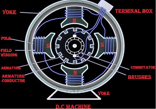
Generally, the alternating voltage is produced in the coil, which is rotating in a magnetic field, but the direct current is required in the external circuit. For this purpose, the commutator is needed. Each commutator segment is connected to the ends of the armature coils. The commutator receives the current from the brushes, which are also placed on the rotating armature.
Ques.17. The loss associated with the mechanical friction of a machine is called (SSC-2018 Set-4)
- Eddy current Loss
- Mechanical Loss
- Hysteresis Loss
- Stray Load loss
Answer.2. Mechanical Loss Explanation:- In the rotating machine whether it is AC or DC machine the type of losses are almost the same The various losses in a d.c. the machine, whether it is a motor or a generator, is categorized amplified into three groups as: Copper losses are also called Electrical losses, winding losses or Ohmic losses. The copper losses are the losses taking place due to the current flowing in a winding. There are basically two windings in a d.c. machine namely armature winding and field winding. The copper losses are proportional to the square of the current flowing Through these winding; Thus the various copper losses can be given by Core losses are also known as iron losses or Magnetic losses. These Losses are constant and independent of the load. They are induced in the machine due to hysteresis and eddy currents produced in the core produced when the magnetization is changing. They mainly occur in the armature teeth and core as also in the pole shoe. Hysteresis losses occur due to the reversal of the magnetization of the armature core. So, the hysteresis loss can be obtained as: Hysteresis Loss = Kh × BM1.67 × f × v watts where The eddy current loss exists due to eddy currents. When the armature core rotates, it cuts the magnetic flux and e.m.f. gets induced in the core. This induced e.m.f. sets up eddy currents which cause power loss. Ibis loss is given by, Eddy current losses = Ke × Bm2 × f2 × t2 Where Ke = Eddy current constant These losses are produced due to friction and windage (friction with air) caused by machine rotation. Hence, these are named as mechanical losses. Some power is required to overcome mechanical friction and wind resistance at the shaft. They depend on the speed of the machine. The mechanical losses are also constant for a d.c. machine Bearing friction loss generally depends on the type of bearing used and on the viscosity of the lubricant. Brush friction loss is proportional to the contact area and the brush pressure. It also depends on the other factors like material of the brush and commutator, their polish condition and the temperature at the contact surface. The magnetic and mechanical losses together are called stray losses. Stray load losses are losses that are produced in the machine when they are loaded. They cannot be considered with the main losses listed above. These losses include: (a) Additional core loss resulting from armature reaction distortion. (b) Copper loss due to short circuit produced in coils, segments, and brushes during commutation. (c) Copper loss due to non-uniform distribution of current in large-sized armature conductors. Stray load losses are very small in value and therefore, they are very difficult to calculate. In small machines, they can be neglected but for large machines, they are generally considered to be 1% of the output power in total.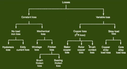
Copper Losses
Core Losses
Kh = Hysteresis constant depends upon the material
Bm = Maximum flux density
f = frequency
v = Volume of the core
t = thickness of the coreMechanical Losses
Stray Load Losses
Ques.18. Armature reaction effect causes flux to reduce with (SSC-2018 Set-4)
- Decreasing Torque
- Increasing Torque
- Increasing current
- Both Increasing torque and increasing current
Answer.3. Increasing current Explanation:- When the load is connected to the DC motor, the armature winding of the DC motor carries a current. Every current-carrying conductor produces its own flux so armature of the DC motor also produces its own flux when carrying a current. So there are two fluxes present in the air gap, one due to armature current while second is produced by the field winding called main flux. The flux produced by the armature is called armature flux So the effect of the armature flux on the main flux affecting its value and the distribution called armature reaction. The armature reaction always results in the reduction of generated e.m.f due to a decrease in the value of flux Per Pole. Armature reaction occurs in DC motors and is caused by the stator magnetic field being distorted, or altered, in reaction to the armature magnetic field. The armature reaction is actually a bending of the motor magnetic field so that the brushes are no longer aligned with the neutral magnetic plane of the motor. If the brushes are not in alignment with this magnetic plane, the current conducted to the armature does not split equally in the armature conductors and therefore causes a voltage difference at the brushes. This causes sparking where the brush meets the commutator. In a motor with a constant load. We know that reducing the flux leads to an increase in speed, so we can now see that in a machine with pronounced armature reaction, when the load on the shaft is increased and the armature current increases to produce more torque, the field is simultaneously reduced and the motor speeds up. Though this behavior is not a true case of instability, it is not generally regarded as desirable! Large motors often carry additional windings fitted into slots in the pole-faces and connected in series with the armature. These ‘compensating’ windings produce an m.m.f. in opposition to the armature m.m.f., thereby reducing or eliminating the armature reaction effect.
Ques.19. The armature of a dc machine is made of (SSC-2018 Set-4)
- Mild Steel
- Silicon Steel
- Stainless steel
- Cast Iron
Answer.2. Silicon Steel Explanation:- The armature winding of the DC motor is connected to a rotating part of the machine called rotor. It goes through an alternating magnetic field. This results in magnetic losses. Because of magnetic losses, the rotor is built using an armature core which in turn is made with much low-hysteresis silicon steel lamination. These laminations are stacked together to create a cylindrical structure thus providing a high resistance path to the eddy currents hence less heat is generated. Hence hysteresis and eddy current losses are reduced by using the silicon steel
Ques.20. DC generators are designed to develop armature voltages not exceeding 650 V because of the limitations of (SSC-2018 Set-4)
- Field winding
- Armature Winding
- Commutator
- Starter
Answer.3. Commutator Explanation:- The armature is rotating in nature in the case of DC machines. We can’t keep armature on stator like in the case of Alternators. In high voltage DC Generators, there is not enough space to keep heavy armature windings on the rotor. In DC machines commutator is present which is absent in the AC Generator. In the construction of the commutator, there are numbers of Coppe segments that are insulated from each other by the thin sheet of mica or other insulation material. The number of commutator segments must be equal to the number of coils in the armature. If the generated voltage is high in DC Generator the insulation required will be more in commutator and the size of the commutator will increase along with the armature. Such a commutator becomes heavy in weight. As the DC generator has brushes and commutators, there is sparking in the assembly and also due to the friction between the brush and commutator, there is more requirement of maintenance. Hence, they are not robust and need frequent maintenance, unlike the AC generators, which don’t have any such parts and the power is directly taken from the steady windings of the stator.