Ques.21. Which of the following generators are used in arc welding (SSC-2018 Set-5)
- Shunt generators
- Series Generator
- Cumulative compound generators
- Differential compound generators
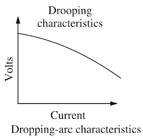
Answer.4. Differential compound generators Explanation:- Arc welding is the widely used method of joining the metal parts. Here the source of heat is an electric arc. Arc welding is a group of welding processes where the heating is produced with an electric arc or arcs, mostly without the application of pressure and with or without the use of fillet metal, depending upon the base plate thickness. ARC Welding Principle In arc welding, the ARC is generated between the positive pole of D.C. (direct current) called anode and the negative pole of D.C. called cathode. When these two poles are brought together, and separated for a small distance (1.5 to 3 mm) such that the current continues to flow through a path of ionized particles, called plasma, an electric arc is formed. Since the resistance of this ionized gas column is high, so more ions will flow from anode to the cathode. Heat is generated as the ions strike the cathode. A.C. or D.C. Machines in ARC Welding Depending upon the application, A.C. or D.C. machines are used in arc welding, but in some cases, either of them can be used. D.C. supply is usually obtained from generators driven by an electric motor or if no electricity is available then the diesel engines can be used. D.C. welding is mostly used for heavy work and at sites where electricity is not available. Arc welding requires a power source that can deliver electrical power at low voltage and high current such that it can establish and sustain an arc plasma column between the welding electrode and the workpiece. The line voltage in the mains supply is too high to be used directly in arc welding. Therefore either a transformer, solid-state inverter/rectifier or a motor-generator set is used to obtain the required open-circuit voltage necessary for arc welding. It is generally in the range of 20-80 V. At the same time the same power source should be capable of delivering high current typically ranging from 50 to 1500 A. This welding power source can have the output of alternating current (AC) or direct current (DC). These power sources have volt-ampere characteristics typically of constant current (CC) or constant potential (CP) type. The output may also have a pulsing mode. A schematic of the basic elements of an arc welding power source is shown in Fig. An arc behaves in a totally different manner from a norms resistance. As the current is increased the potential drop across the arc, instead of increasing as with an ohmic resistance, decreases up to a current of the order of 50-70 A, and then becomes approximately constant. This is because with increasing current arc increases in size, allowing a larger area for curve flow, and also increases in temperature becoming thereby more conducting. The generator used for welding purposes should have high current and low voltage which can be obtained by the differential compound generator. Differentially compounded DC generator has drooping characteristics that mean if load current increases the net flux will decreases(i.e shunt field and series fields in opposition will increases)due to demagnetization effect hence the Induced EMF and terminal voltage decreases.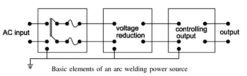
Ques.22. Maximum power will be developed when back emf is (SSC-2018 Set-5)
- Equals to supply voltage
- Half to supply voltage
- Doubles to supply voltage
- All option are correct
Answer.2. Half to supply voltage Explanation:- Suppose a d.c motor of resistance R is connected to a d.c. supply of V volts. Let the armature current be la and the back E.M.F developed be Eb. The voltage equation of the D.C motor is given as V = Eb + IaRa ————(1) Multiplying both sides of the above equation by Ia we get VIa = EbIa + I2aRa ———(2) This equation is called the power equation of a dc motor. VIa = electric power supplied to the armature (armature input). EbIa = power developed (mechanical power) by armature (armature output). I2aRa = Electric power wasted in the armature (armature copper loss) Thus out of the armature input, a small portion is wasted as I2aRa loss and the remaining portion EbIa is converted into mechanical power within the armature. Now the mechanical power developed by the motor is Pm = EbIa Putting the value of Pm in equation 2 we get VIa = Pm + I2aRa or Pm = VIa − I2aRa Since V and R are fixed, the power developed by the motor depends upon armature current. For maximum power, dPm ⁄ dIa should be zero. dPm ⁄ dIa = VIa − I2aRa = 0 dPm ⁄ dIa = V − 2IaRa = 0 IaRa = V/2 Putting the value of IaRa in equation 1 we get V = Eb + V/2 Eb = V/2 Hence mechanical power developed by the motor is maximum when back e.m.f. is equal to half the applied voltage. In practice, we never try to achieve this condition because in that case, the armature current will be much more than the normal current. Moreover, half of the input power would be wasted in the armature resistance in the form of heat and taking other losses into consideration, the motor efficiency will be below 50 percent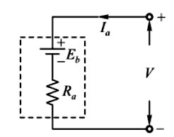
Ques.23. No-load saturation characteristics are plotted between (SSC-2018 Set-5)
- No-load voltage and field current
- No-load voltage and armature current
- Short circuit current and field current
- Short circuit current and armature current
Answer.1. No-load voltage and field current Explanation:- No-load saturation characteristic of the generator: This curve is also called magnetic characteristic or open-circuit characteristic (O.C.C.). It shows the relationship between the e.m.f. generated on no-load in the armature, Eo, and the field current if, with the speed remaining constant. The curve depends on the material used in the electromagnets. It is practically the same, whether the generator is separately-excited or self-excited. Generally, it starts from zero but in a self-excited DC generator, it has residual voltage and starts al slightly higher value. At the low voltage and, hence, low levels of flux, the major reluctance (magnetic resistance) of the magnetic circuit is the airgap. In the linear portion of the open-circuit curve, terminal voltage and flux are proportional to the field current. This portion of the open-circuit saturation curve, which is linear, is called the “airgap line.” At higher voltages as the flux increases the stator and rotor iron saturate and additional field current is required to drive magnetic flux through the iron. This is due to the apparent higher reluctance of the magnetic circuit. Hence, the upper part of the curve bends away from the airgap line at an exponential or logarithmic rate, dependent on the saturation effect in the stator and rotor. Without the presence of iron in the circuit, the airgap line would continue on linearly, meaning that the terminal voltage and machine flux would increase in linear proportion to the increase in field current.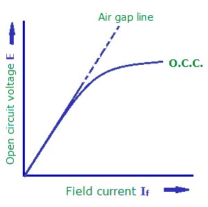
Ques.24. Which of the following motor is suitable for driving cranes, hoists, centrifugal pumps, conveyor belt, etc.? (SSC-2018 Set-5)
- DC Series Motor
- DC Shunt Motor
- DC compound Wound Motor
- Any of these
Answer.1. DC Series Motor Explanation:- Hoists Hoists are a means of transporting materials or passengers vertically by means of a moving level platform. Materials hoist come in basically two forms i.e static and mobile models. The hoist can be driven by petrol, diesel, or electric motor and can be of a cantilever or enclosed variety. Crane A crane is the type of machine mainly used for handling heavy loads in different industry branches: metallurgy, paper, and cement industry. By the construction, cranes are divided into the overhead and gantry cranes Belt Conveyors are designed to carry a wide variety of bulk materials and packed bags, boxes, pouches etc for various industries. Belt conveyors are economical and efficient conveying of materials over long distances, either in horizontal or limited inclines. It conveys a high capacity of materials for lumpy ore stone, coal and wood logs. Torque and power requirements for crane and Hoist drives and Belt conveyor Speed control is an essential feature in crane drives. It is required for allowing soft starting and stopping of the travel motions for enabling its correct positioning of the load. For the lifting drive the speed control in a wide speed range, from zero to nominal values, is required. Because of the precision when raising and lowering load, the possibility of working at a very low speed and hold a load at the standstill is required, without using the mechanical brakes. The torque and power that have to be delivered by the drive may be obtained from the torque versus speed characteristic from the load (so-called mechanical characteristics) and the differential equation of motion. During acceleration, kinetic energy is stored in the system. To stop the crane, this energy must be absorbed by the drive. The acceleration and retardation must be uniform. For the exact positioning of loads creep speeds must be possible. The motion of the crane is in all three dimensions. The drive must have high speeds in both directions horizontal and vertical. The speed must be constant while lowering the loads. Mechanical braking must be available in an emergency. Due to the heavy inrush of current at starts, fluctuations in supply voltage are possible. The drive motor must be capable of withstanding such fluctuations. Crane hooks have to be moved in three dimensions in space: two in a horizontal plane and a vertical hoist motion. The characteristics of long travel and cross travel motions are: Hoist motion: This is required to lift and put down the loads without damage. The characteristics of this motion therefore are: The nature of the duty cycle and conditions under which it has to work forms the basis of the requirements of the crane. In steel plants, the cranes to be used must satisfy the following: Among the d.c. motors, the series motors, and cumulative compound motors are most preferred for crane operations. The motors have good starting torque, high torque capacity at light loads, the simple arrangement of braking, electric braking at low speeds is possible. The only disadvantage is that the motors are less stable while the regenerative braking. So additional stabilizing circuits are necessary. Advances made in the technology of solid-state devices have enabled the use of thyristor converters and choppers for driving the d.c. motors used in cranes and hoists with good accuracy, reliability, and efficiency. Ward Leonard system is commonly employed for elevators, hoists, and main drive in steel mills, as this method can give unlimited speed control in either direction. Since the generator voltage can be varied gradually from zero, no extra starting equipment is required to start up the main motor smoothly. Note:- Centrifugal pumps and fans are constant displacements with normal starting torque devices, therefore, DC shunt Motor or squirrel cage induction motor is usually preferred.
Ques.25. The field control of a DC shunt motor gives (SSC-2018 Set-6)
- Constant torque drive
- Constant kW drive
- Constant speed Drive
- Variable load speed drive
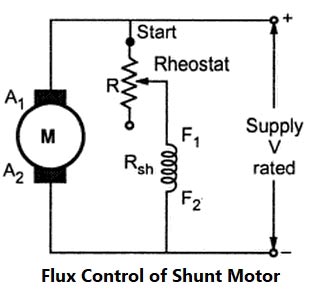
Answer.2. Constant kW drive Explanation:- In the field control operation, if the armature current is not allowed to change beyond rated value, the reduction in field flux reduces the torque developed with the increase of speed. In this method, armature voltage is kept constant and the field voltage is varied. Thus, the product of torque and speed i.e power remains approximately constant. Hence, the field control operation is called a constant power (Constant kW) operation. The speed of DC Shunt Motor is inversely proportional to the flux and the flux is directly proportional to the Torque. The flux is dependent on the current through the shunt field winding. Thus flux can be controlled by adding a rheostat (variable resistance) in series with the shunt field winding. At Starting the rheostat R is kept at the minimum. The supply voltage is at its rated value. So the current through shunt field winding is also at its rated value. Hence the speed is also rated speed i.e at normal speed. When the resistance R is increased due to which shunt field current Ish decreases, hence decreasing the flux produced. As N =(I/Φ), the speed of the motor increases beyond its rated value. Now as we know that the speed of DC motor is directly proportional to the flux hence when the speed is increased the back EMF also increased. Thus by this method, the speed control above the rated value is possible. Field Control F is controlled by tapping series field turns or by a diverter resistance across the The highest speed achieved in this method is limited by the following reasons: 1. The increase in armature current causes overheating of the armature. 2. Due to high speed, centrifugal stresses are set up in the armature. 3. Because of an increase in the armature current, the increased armature reaction, under the field condition, gives rise to the instability of motor at high speed, coupled with poorer commutation. NOTE:- Armature voltage control is constant torque drive. This method is employed for speeds above base speed The full load speed at full rated current and rated armature voltage is called the base speed. For operating below base speed, the field flux is kept at full excitation and the applied voltage to the armature is reduced. As the speed decreases the back emf reduces and so the armature current remains practically constant. Since the field flux and the armature current are constant in the armature control method, this method of speed control is called constant torque operation.Flux Control Method or Field control method
series field.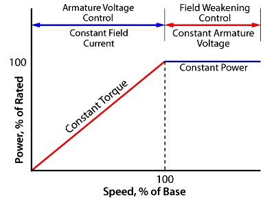
Ques.26. A lap wound dc machine has 400 conductors and 8 poles. The voltage induced per conductor is 2V. The machine generates a voltage of (SSC-2017)
- 100 V
- 200 V
- 400 V
- 800 V
Answer.1. 100 V Explanation: For lap wound number of parallel paths is equal to the number of poles Number of the conductor in each parallel path = 400/8 = 50 Generated E.M.F = 50 x 2 = 100V
Ques.27. A series drawing an armature current of Is is operating under saturated magnetic conditions, the torque developed in the motor is proportional to (SSC-2017)
- 1/Ia
- 1/I2a
- I2a
- Ia
Answer.4. Ia Explanation: We know Torque Tα ΦIa As the motor is operating under saturation condition so torque will be independent of flux i.e. T α Ia.
Ques.29. Two D.C. machines 500 kW each are tested by the Hopkinson testing method. The power input would be (SSC-2016)
- 100 kW
- 1000 kW
- 500 kW
- None of the above
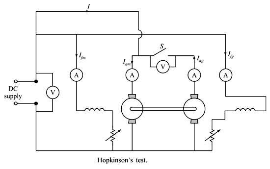
Answer.1. 100 kW Explanation:- Hopkinson’s test is also referred to as the regenerative or Back-to-Back test. In Hopkinson’s test, we require two identical dc machines. This is a regenerative test. Both the dc machines are mechanically and electrically coupled and are tested simultaneously. One of the machines will act as a dc motor and the other as a dc generator. The motor will rotate the generator and the generator will supply power to the motor. Now the question arises, if both machines help each other, then which one will supply the losses. The answer is external dc supply, that means, the input of the external supply will provide the power losses of both the machines. Now the voltage across switch S should be zero and only then we can declare that similar polarities of the machines are connected. So, when the switch S is closed both the dc machines are in perfect parallel connection and there is no chance of the presence of circulating currents between the two machines. Since in case of the generator, the induced emf minus the armature drop is the terminal voltage and in case of the motor the induced emf plus the armature drop is the terminal voltage, the excitation of the generator will be more than the excitation of the motor to maintain the terminal voltages equal to one another. Obviously, the no-load iron loss and stray loss will not be equal for both the machines even though the machines are identical in all respects. Stray load loss is a very important factor in determining the efficiency of a dc machine. If we ignore this, we cannot determine the actual efficiency of the dc machine properly due to the following reasons. Stray load loss is the additional copper loss which occurs in the conductors an account of the non-uniform distribution of alternating currents. This increases the effective resistance of conductors and that is nothing but the skin effect. When the conductors carry load current, the teeth of the core get saturated and as a result, more flux passes down the slots through the copper conductors and thus setting up the eddy current losses in them. Due to the flux distortion, the net increase in the core loss occurs and the extra core loss is nothing but the core stray load loss. Thus the total power drawn from the supply is only for supplying internal losses of the two machines. Thus even very large machines may be tested as the power required is very small. Hence the power input in the given question will be 100 Watt. Advantages The various advantages of Hopkinson’s test are, Disadvantages:- The various disadvantages of Hopldnson’s test are,Hopkinson’s Test
Ques.30. The number of conductors of the compensating winding in a D.C. machine (SSC-2016)
- Is always less than the number of armature conductors per pole
- Is always more than the number of armature conductors per pole
- Maybe less or more than the number of armature conductors per pole
- None of these
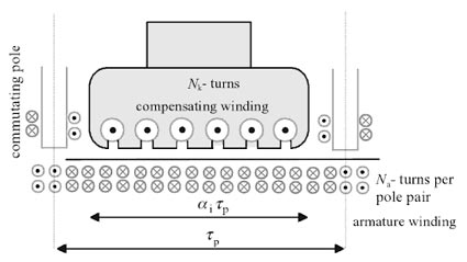
Answer.1. Is always less than the number of armature conductors per pole Explanation:- The purpose of compensating windings in DC machines is to compensate for harmful flux components created by armature windings. Flux components are harmful because they create an unfavorable air-gap flux distribution in DC machines. Compensating winding is connected in series with the armature winding in such a way that the current flowing in them is directly opposite to the current flowing in the armature located just below the pole faces. The MMF produced by the compensating winding is equal and opposite to the MMF produced by the armature at every point under the pole faces. Hence, the net MMF is just equal to the MMF produced by the main poles alone. As a result, the flux in the machine remains unchanged regardless of the load on the machine. Let the number of armature conductor = Z/P Number of armature conductors per pole = Z/2P Number of armature turns at any instant under one pole= Pole arc/Pole Pitch × Z/2P No. of armature amp-turns/pole for compensating winding = 0.7 × Z/2P Hence from the above equation, it is clear that the number of conductors of the compensating winding in a D.C. machine is always less than the number of armature conductors per pole.