Ques.91.A reverse Biased PN Junction will act as an
Amplifier
Open switch✓
Closed Switch
Attenuator
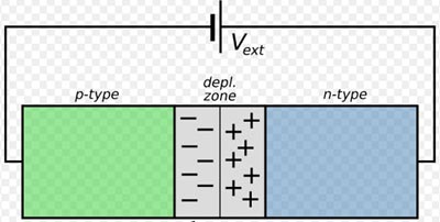
In the reverse-biased p-n junction diode, the positive terminal of the battery is connected to the n-type semiconductor material and the negative terminal of the battery is connected to the p-type semiconductor material.
In reverse biasing, free electrons and holes move away from the junction. Hence, increasing the width of the depletion layer. As the depletion layer increases, the potential barrier also increases.
The majority of charge carriers cannot move across the junction, hence current will not be allowed to flow across the diode. That is, on reverse biasing, the P-N junction diode acts as an insulator or as an Open switch.
An ideal diode acts as an open circuit under reverse bias conditions. A practical diode offers large but not infinite resistance under reverse bias conditions.
A diode conducts current when forward biased and blocks current when reverse biased.
The current flowing in the reverse-biased circuit due to the minority charge carrier is known as reverse current.
Ques.92. The peak inverse voltage, in the case of a bridge rectifier, for each, the diode is: (where Eo = Peak value of input voltage)
Eo✓
2Em
3Em
4Em
Peak inverse voltage. Peak inverse voltage (P.I.V) is the maximum voltage across the diode when it is not conducting. This happens during the negative half of the applied voltage when the diode does not conduct. At this stage, the voltage across the diode is equal to the applied voltage.
Peak Inverse Voltage of the bridge Rectifier:-
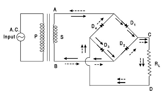
BridgeRectifier:- A bridge circuit acts as a full-wave rectifier without the use of a center-tapped transformer. It consists of four diodes in two pairs D1, D3, and D2, D4, connected to form a bridge as shown in Fig. The A.C supply to be rectified is applied to the diagonally opposite ends of the bridge through a transformer. The load resistance RL is connected between the other Iwo ends of the bridge.
Working:- During the positive half cycle of A.C when the end A of the secondary of the transformer is positive and the end B is negative the diodes D1, D3 are forward biased while the diodes D2, D4 are reverse biased. Therefore, only the diodes D1, D3 conduct and the direction of flow of current is as shown by full line arrows. The current flows from A to The first diode D, to C, through the load resistance RL lo D, to The second diode D3, and then to B. thus completing the circuit.
During the negative half-cycle when the end B of the secondary of the transformer is positive and the end A is negative the diodes D2, D4 are forward biased, whereas the diodes D1, D3are reverse biased. Therefore. only the diodes D2, D4 conduct and the direction of flow of current is shown by dotted line arrow heads. The current flows from B to the first diode D2 to C through the load resistance RL to D, the second diode D4 and then to A thus completing the circuit. During both the half cycles the current through the load resistance RL, flows in the same direction l.e., C to D. The peak inverse voltage of each diode is equal to the maximum secondary voltage, Eo of the transformer as proved below.
Peak inverse voltage:- If during the half-cycle of a c. input the end A of the secondary of the transformer is positive and end B is negative, diodes D1 and D3 are forward biased, while the diodes D2 and D4 are reverse biased. Since the diodes are considered ideal. the diodes D1 and D3 have negligible forward resistance and can be taken to be simple connecting wires. In such a case the two reverse-biased diodes D2 and D4 and the secondary of the transformer are in parallel. Hence the peak inverse voltage of each diode D2 or D4 is equal to the maximum Eo across the secondary. Similarly, during the next half-cycle, D2 and D4 are forward biased and can be taken to be simple connecting wires. In such a case diodes D1 and D3 and the secondary of the transformer are in parallel. Hence again the peak inverse voltage of D1 or D3. is equal to the maximum voltage Eo.
Hence each diode has only transformer voltage across it on the inverse cycle. In the other words, the peak inverse voltage is equal to the peak transformer secondary voltage Em or Eo
Ques.93. In an electronic circuit, the transistor is used for switching ON and OFF a relay, when the transistor switches OFF the relay, a higher voltage appears across the transistors. How can a transistor be protected from this voltage?
A capacitor in series to the relay
A resistor in series to the relay
An inductor parallel to the relay
A diode parallel to the relay✓
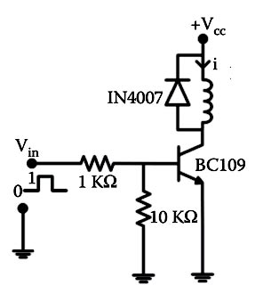
Consider a relay control circuit with Darlington’s pair of transistors. When the base voltage of the transistor is zero (or negative), the transistor is cut off and acts as an electrically open circuit. In this condition, no collector current flows to the emitter, and the relay coil is de-energized because, being current devices, if no current flows into the base, then no current will flow through the relay coil. If a large enough positive current is now driven into the base to saturate the transistor, the current flowing from base to emitter controls the larger relay coil current flowing through the transistor from the collector to the emitter.
When the current is flowing through the coil, the relay gets energized and the corresponding action happens as discussed above. As we know, the relay coil is not only an electromagnet, it is also an inductor. When power is applied to the coil due to the switching action of the transistor, a maximum current will flow as a result of the DC resistance of the coil as defined by Ohm’s Law (I = V/R). Some of this electrical energy is stored within the relay coil as the magnetic field.
When the transistor is turned off, the current flowing through the relay coil decreases, and the magnetic field collapses. However, the stored energy within the magnetic field has to go somewhere and a reverse voltage is developed across the coil as it tries to maintain the current in the relay coil. This action produces a high voltage spike across the relay coil that can damage the switching operation of the transistor.
Hence, in order to prevent damage to the transistor, a freewheeling diode is connected across the relay coil, as shown in the figure. This flywheel diode clamps the reverse voltage across the coil to about 0.7 V, dissipating the stored energy and protecting the switching transistor.
or
When the transistor is off then the flywheel diode will conduct and the potential across the transistor is the conduction voltage of the diode (0.2 – 0.7), hence protecting the transistor from high voltage.
Ques.94. The efficiency of the class B amplifier approximatley:
10% to 30%
30% to 50%
60% to 80%✓
70% to 100%
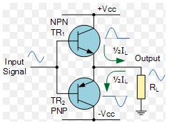
Class B Amplifier also is known as a push-pull amplifier configuration.
Class-B amplifiers use two or more transistors biased in such a way that each transistor only conducts during the one-half cycle of the input waveform.
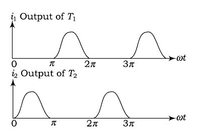
When the operating point is selected at one end of the load line, the output signal is only available for 50% of the complete cycle at the output of the amplifier, and this type of amplifier is called a class B amplifier. The conduction of the transistor is only for half of the cycle and in the remaining portion of the cycle, the current at the output is either zero or maximum. In a class B amplifier, the output current is of the form of the current that of the half-wave rectifier. The transistor is an active region for 50% of the cycle, producing a sinusoid signal of conduction angle of 180° at the output of the circuit. The waveform of the current at the output of a class B amplifier is as shown in Fig.
Since the conduction period of the transistor has reduced to 50% compared to that of a class A amplifier. Class B provides better efficiency than Class A, achieving maximum efficiency of η = π/4 = 79 %.
For the remaining 50% of the cycle, the transistor is either in the cut-off of saturation, thus leading to nonlinearity and hence the generation of harmonics. The harmonic content in the output of this circuit is high compared to that of class A.
Advantages of Class B Push-Pull Amplifiers
The conversion efficiency of a Class B push-pull amplifier is 78.5% whereas the conversion efficiency of a Class A amplifier is 25%. This is possible as no power is drawn from the dc power supply when there is no input signal.
All even harmonics are eliminated in the ac output signal of a Class B push-pull amplifier.
Due to the absence of even harmonics, this amplifier circuit provides more output per transistor for a given amount of distortion.
It is used as an audio Amplifier.
Ques.95. The oscillations in a synchronous motor can be damped out by
Maintaining constant excitation
Providing damper bars in the rotor poles faces✓
Running the motor on the leading power factor
Oscillation cannot be damped
Hunting:
Sudden changes of load on synchronous motors may sometimes set up oscillations that are superimposed upon the normal rotation, resulting in periodic variations of a very low frequency in speed. This effect is known as hunting or phase-swinging.
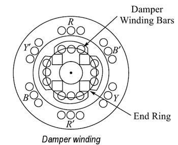
Use of Damper winding to prevent Hunting
Damper windings are windings that are wound to the rotor poles of the machine (winding is similar to that of an induction machine) which help in two ways.
We all know that a synchronous machine is not self-starting. Thus providing damper windings helps synchronous machines act as an induction motor ( only at starting). Which helps the machine to self-start.
We all know that hunting is a persistent phenomenon when it comes to synchronous machines.
During Hunting, the rotor of the synchronous motor starts to oscillate in its mean position, therefore, a relative motion exists between damper winding, and hence the rotating magnetic field is created. Due to this relative motion, e.m.f. gets induced in the damper winding. According to Lenz’s law, the direction of induced e.m.f. is always so as to oppose the cause producing it. The cause is hunting. So such induced e.m.f. oppose the hunting. The induced e.m.f. tries to dampen the oscillations as quickly as possible. Thus hunting is minimized due to damper winding.
Ques.96. An over-excited synchronous motor is used for
Variable speed load
Low torque loads
Power factor corrections✓
High torque loads
An overexcited synchronous machine produces reactive power whether or not it is operating as a motor or as a generator.
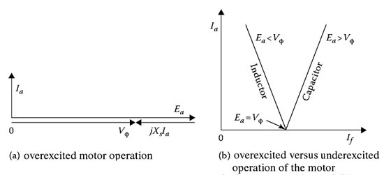
When synchronous motors are used as synchronous condensers they are manufactured without a shaft extension, since they are operated with no mechanical load. The ac input power supplied to such a motet can only provide for its losses. These losses are very small and the power factor of the motor is almost zero.
Therefore, the armature current leads the terminal voltage by close to 90°, as shown in Figure a, and the power network perceives the motor as a capacitor bank. As can be seen in Figure b, when this motor is overexcited it behaves like a capacitor (i.e., synchronous condenser), with Ea > Vφ, whereas when it is under-excited, it behaves like an inductor (i.e., a synchronous reactor), with Ea < Vφ.
Synchronous condensers are used to correct power factors at load points or to reduce line voltage drops and thereby improve the voltages at these points, as well as to control reactive power flow. Generally, in large industrial plants, the load power factor will be lagging. The specially designed synchronous motor running at zero loads, taking a leading current, approximately equal to 90°. When it is connected in parallel with inductive loads to improve power factor.
Large synchronous condensers are usually more economical than static capacitors.
Ques.97. When any one-phase of a 3-phase synchronous motor is short-circuited, the motor
Will overheat in the spot
Will refuse to start✓
Will not come upto speed
Will fail to pull into step
When any one-phase of a 3-phase synchronous motor is short-circuited, the motor will refuse to start.
Failure of a synchronous motor to start is often due to faulty connections in the auxiliary apparatus. This should be carefully inspected for open circuits or poor connections. An open circuit in one phase of the motor itself or a short circuit will prevent the motor from starting. Most synchronous motors are provided with an ammeter in each phase so that the last two causes can be determined from their indications: no current in one phase in case of an open circuit and excessive current in case of a short circuit. Either condition will usually be accompanied by a decided buzzing noise, and a short-circuited coil will often be quickly burned out. The effect of a short circuit is sometimes caused by two grounds on the machine.
Difficulties in starting synchronous motors:- A synchronous motor starts as an induction motor. The starting torque, as in an induction motor, is proportional to the square of the applied voltage. For example, if the voltage is halved, the starting effort is quartered. When a synchronous motor will not start, the cause may be that the voltage on the line has been pulled below the value necessary for starting. In general, at least half the voltage is required to start a synchronous motor.
Difficulty in starting may also be caused by an open circuit in one of the lines to the motor. Assume the motor to be three-phase. If one of the lines is open, the motor becomes single-phase, and no single-phase synchronous motor, as such, is self-starting. The motor, therefore, will not start and will soon get hot. The same condition is true of a two-phase motor if one of the phases is open-circuited.
Difficulty in starting may be due to a rather slight increase in static friction. It may be that the bearings are too tight, perhaps from cutting during the previous run. Excessive belt tension, if the synchronous motor is belted to its load or any cause which increases starting friction will probably give trouble. Difficulty in starting may be due to field excitation on the motor. After excitation exceeds one-quarter of the normal value, the starting torque is influenced. With full field on, most synchronous motors will not start at all. The field should be short-circuited through a proper resistance during the starting period.
This test is conducted with voltages from 500 to 5000 V and provides information on the condition of machine insulation. A clean, dry insulation system has very low leakage as compared to a wet and contaminated insulation system. This test does not check the high-voltage strength of the insulation system but does provide information on whether the insulation system has high leakage resistance or not. This test is commonly made before the high-voltage test to identify insulation contamination or faults. This test can be made on all or parts of the machine circuit to the ground. i.e
Field winding test or Rotor winding Test
Overall Stator Armature winding test
Overall System test for the Motor or generator
The overall system test includes generator neutral, transformer, all stator windings, isolated phase bus, and low side windings of the generator step-up transformer. This test is performed as a screening test after an abnormal occurrence on the machine. If the reading is satisfactory, no further tests are made. If the reading is questionable or lower, the machine terminals are disconnected and further isolation is performed to locate the source of the trouble.
Ques.99. The speed of a synchronous motor can be changed by
Changing the supply voltage
Changing the frequency✓
Changing the load
Changing the supply Terminals
The speed of the synchronous motor is given as
Ns = 120f/P
Therefore by changing the number of poles and frequency, we can change the speed of the synchronous motor.
Ques.100. The under-excited synchronous motor takes____
Leading current
Lagging current✓
Both leading and lagging current
None of these
Unlike induction machines, the synchronous machines can operate at lagging, leading, and unity power factors. In an induction machine, the magnetizing current is required to establish flux in the air gap. This magnetizing current lags the voltage and therefore, the induction machine always operates at a lagging power factor.
On the other hand, in the synchronous machine, the total air gap flux is produced by the dc source and there is no use of lagging current from ac system for the production of air-gap flux. If dc excitation is decreased, lagging reactive power will be drawn from ac source to aid magnetization and thus machine will operate at a lagging power factor. If dc excitation is more, the leading current is drawn from the ac source to compensate (oppose) the magnetization and the machine will operate a leading power factor.
Thus it can be concluded that an over-excited motor(Eb > V) draws a leading current (acts like a capacitive load) but an under-excited motor(Eb < V) draws a lagging current (acts as an inductive load).
For SSC JE 2018 SET-1 Electrical paper with complete solutionClick Here
For SSC JE 2017 Electrical paper with complete solutionClick Here
For SSC JE 2015 Electrical paper with complete solutionClick Here
For SSC JE 2014 (Evening shift) Electrical paper with complete solutionClick Here
For SSC JE 2014 (Morning shift) Electrical paper with complete solution Click Here
For SSC JE 2013 Electrical paper with complete solutionClick Here
For SSC JE 2012 Electrical paper with complete solutionClick Here
For SSC JE 2011 Electrical paper with complete solution Click Here
For SSC JE 2010 Electrical paper with complete solution Click Here
For SSC JE 2009 Electrical paper with complete solution Click Here