Ques.31. What will be the instantaneous value of the alternating current (in A) which is represented by i(t) = 20 sin (13t − 20) A, when the value of t is 5?
0
10
14.14✓
17.32
Let the expression be as follows:-
I(t) = Im sin(ωt ± φ)
Where φ represent the concerned phase-shift
Im = Maximum value of the current
Time t = 5 sec
I(t) = 20 sin(13t − 20)A
I(t) = 20 sin(13 × 5 − 20)
I(t) = 20sin(65 − 20)
I(t) = 20sin(45)
I(t) = 14.4 A
Ques.32. What is the peak value of the alternating voltage (in V) having an average value of 180 V?
254.59
282.57✓
333.34
359.96
The mean or average value of an alternating voltage or current for one alternating (half-cycle) is 63.7% of the peak (or maximum) value.
Iavg = 0.637IO
180 = 0.637IO
Io = 282.57
Ques 33. The capacitive reactance of a circuit is 60 ohms when it is supplied with a 50 Hz supply. What will be the value of the capacitive reactance (in ohms) of the same circuit, if it is supplied with a 60 Hz supply?
50✓
60
75
125
Given
Capacitive reactance XC1 = 60 Ω
Frequency f = 50 Hz
Now the frequency is 60 Hz
Capacitive reactance XC2 = ?Ω
Capacitance C1 = C2
Capacitive Reactance is given as
XC = 1/2πfC
XC1 ⁄ XC2 = 2πfC1 ⁄ 2πfC2
60 ⁄ XC2 = 60 ⁄ 50
XC2 = 50Ω
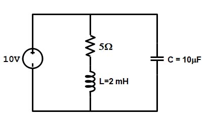
Ques.34. A parallel RLC circuit is being supplied by a DC source as shown in the figure below. What is the value of the current flowing through the capacitor (in A)?
0✓
0.5
1
2
An inductor is a passive element that stores the magnetic energy inside its Magnetic field when an alternating current flows through it.
We know, by Faraday’s law, that when an alternating current flows through a coil, it induces a magnetic field around it. This magnetic field, in turn, creates a varying magnetic flux. And this varying flux induces an emf whose direction is given by Lenz’s law. Hence we write,
E = – L*(di/dt)
Suppose that a dc circuit contains an inductor. The inductor current, like every other voltage and current in the dc circuit, will be a constant function of time. The inductor voltage is proportional to the derivative of the inductor current, v = L(di/dt), when we supply DC to an inductor, there is no change in current, and hence no varying magnetic flux is created. Due to the absence of a magnetic field, no emf is Induced. So, the voltage across the inductor is zero. Hence, the inductor acts as a short circuit when supplied with DC.
Similarly, the voltage of a capacitor in a dc circuit will be a constant function of time. The capacitor current is proportional to the derivative of the capacitor voltage, i = C (dv/dt),
when a capacitor is connected to a DC circuit, it sees a DC voltage, but takes time to attain that voltage. So, if it has no initial charge, the moment it’s connected, it would start carrying the short circuit current, so it’s initially like a connecting wire. However, the voltage across it increases gradually (depending on the current supplied) to the voltage across the terminals in its absence, and once it does, it prevents any furthermore current, and it’s equivalent to an open circuit.So the capacitor current is zero. Consequently, the capacitor acts like an open circuit.
or
The current in the capacitor can flow only when the voltage across it changes.
If the constant voltage is applied across the capacitor, the capacitor current is zero. This means that the capacitor behaves as an open-circuit (zero current) for d-c voltage.
XC = 1/2πfC
f = 0
XC = Infinite
Now Coming back to the Question
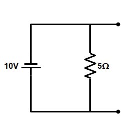
Now the circuit can be Redraw as
Hence the current through the capacitor is zero because the capacitor is an open circuit for DC Source.
Ques.35. Calculate the value of phase angle (in Degrees) in a series RC circuit having a resistance of 50 Ohms and the capacitive reactance of 86.6 Ohms, when supplied with a frequency of 50 Hz.
15
30
45
60✓
The phase angle of series RC circuit is given as
φ = tan−1XC/R
φ = tan−186.6/50
φ = tan−11.1732
φ = 60°
Ques.36. What is the value of the total impedance (in Ohms) of a tank circuit working at the resonant frequency having a capacitance of 0.01 mF and an inductance of 0.01 mH?
0
10
100
Infinity✓
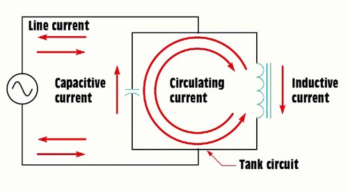
A parallel LC circuit is sometimes called the tank circuit. When a capacitor and an inductor are placed in parallel, they will interchange any applied energy and, thus, share in il storage. When values of inductive reactance and capacitive reactance become equal, they are said to be resonant. In a parallel circuit, inductive current and capacitive current cancel each other because they are 180° out of phase with each other. For any particular generator voltage, there will be a maximum amount of energy that can be impressed on the parallel circuit, and if XL = XC, there will be equality in the energy sharing process of the resonant circuit.
Consequently once a parallel resonant circuit has been charged by the source, it will no longer accept any more energy if both the inductor and the capacitor have no resistive components. In such an instance, the current flow from the generator would be zero because the circuit impedance would be infinite. The interchange of energy rates conforms to the frequency of the resonant circuit and is illustrated in Figure. This energy interchange is known as the flywheel effect and occurs at a frequency rate determined by the inductor and capacitor size.
With a smaller capacitor, less energy is stored and the charge and discharge are more rapid, resulting in higher frequency. A smaller inductor will also increase the frequency, Larger inductors or capacitors (or both will reduce the frequency of energy interchanged.
With equal reactances, the power drawn by the load would be equal to voltage times the load current. With no load connected to the parallel resonant circuit, there would be a minimum of current drawn from the generator and, whatever the current, would serve to replenish losses incurred because of circuit resistances (most of which would be coil resistance). Circuit impedance would be Z = V/I and would be of infinite value with zero current. However, the circulating current between the inductor would be high because of the energy interchange between them.
Ques.37. Calculate the time (in seconds) taken by the series RL circuit having an inductance of 0.6 H and resistance of 30 Ohms to reach a steady-state value.
0.02
0.05
0.1✓
0.5
The time taken by the RL circuit to reach a steady state is 5 times the constant of the RL circuit i.e
Total time = 5τ
Also, the time constant of RL circuit is given as τ = R/L
Total time = 5 × R/L
= (5 × 6) ⁄ 30
= 0.1 sec
Ques.38. Which of the following is NOT correct about a star-connected balanced 3-phase circuit?
The phase current is equal to the line current
The phase voltage is equal to the line voltage
The system does not contain a neutral point✓
It is a four-wire system
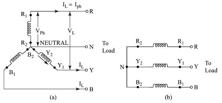
The star connection is formed by connecting the starting or finishing ends of all the three windings together. A fourth conductor which is taken out of the star point is called the neutral point. The remaining three ends are brought out for connection to load. These ends are generally referred to as R-Y-B, to which load is to be connected. The star connection is shown in Fig. In a star connection, we know that each phase is displaced in space by 120° from each other.
This is the three-phase four-wire star-connected system. If no neutral conductor is taken out from the system it gives rise to a three-phase, three-wire star-connected system.
The current flowing through each line conductor is called line current, IL in the star connection the line current is also the phase current. Similarly, the voltage across each phase is called phase voltage, Vph. The voltage across any two line conductors is called line voltage, VL. When a balanced three-phase load is connected across the supply terminals R, Y, and B currents will flow through the circuit. The sum of these currents, i.e., IR, IB, and IY will be zero. The neutral wire connected between the supply neutral point and the load neutral point will carry no current for a balanced system.
Note:- In Delta connected system there is no Neutral Point.
Ques.39. A 3-Phase delta-connected system is supplied by the line voltage of 400 V. The value of the phase current is 70 A. What is the power (in kW) consumed by the system, if the current lags the voltage by 60°?
16.8
42✓
67.2
84
The power consumed by the three-phase circuit is
P = 3 Vph Iph cosφph
In delta connected system
Line voltage is equal to the phase voltage i.e
VL = VPH
∴ P = 3 × 400 × 70 × cos60°
P = 4200 watts or 42 kW
Ques.40. What is the apparent power of a 3-phase star connected system having a line voltage of 250 V and a line current of 40 A and the phase difference between the voltage and current is 36.87 degrees?
13.856 kW
13.856 kVA
17.32 kW
17.32 kVA✓
The total apparent power consumed by any balanced three-phase star connection system is given as