Ques.41. Which of the following is the dimension of resistance?
[M.L2.T-2]
[M.L2.T-2.I-2]
[M L2 T -3 A-2]✓
[M L2 T -2 A⁻1]
Firstly consider the resistance.
Ohm’s law states that the electric current flowing through the conductor is directly proportional to the potential difference between its two ends when the temperature and other physical parameters of the conductor remain unchanged.
V = IR
⇒ R = VI
Now V has units of (electric field)*(distance).
But the electric field has units (force)/(charge).
Also, charge has dimensions of (current)(time) and force has dimensions (mass)(length)/(time)^2.
Thus, dimensions of V is,
[V] = LMLT−2 ⁄ AT
⇒ [V] = M L² T ⁻³ A⁻¹
Dimensional formula for I = A
Put these values in equation (1), we get:
The dimensional formula for R = M L2 T−3 A−1/ A
Dimensional formula for R = [M L2 T −3 A−2]
Ques.42. A factory runs in 3 shifts of 8 hours each, in which it consumes 30 kW, 15 kW, and 25 kW respectively. Calculate the energy consumed by the factory per day.
186.67 kW
373 kW
560 kW✓
746.67 kW
Energy consumption or power consumption refers to the electrical energy per unit of time is given as
E = Power × Time = P × T
Shift 1 energy consumption
E1 = 30 x 8 = 240 kW
Shift 2 energy consumption
E2= 15 x 8 = 120 kW
Shift 3 energy consumption
E3 = 25 x 8 = 200 kW
Total energy consumption
E = E1 + E2 + E3
E = 240 + 120 + 200 = 560 kW
Ques.43. In two wattmeter method of power calculation of a 3-phase balanced star connected system, what is the power factor of the system if one of the wattmeters shows zero reading and the other shows a positive reading?
0
Greater than 0 but less than 0.5
0.5✓
Greater than 0.5 but less than 1
The reading of two wattmeters can be expressed as
W1 = VLILcos(30 + φ) W2 = VLILcos(30 − φ)
(i) When PF is unity ( φ = 0°)
W1 = VLILcos30° W2 = VLILcos30°
Both wattmeters read equal and positive reading i.e upscale reading
(ii) When PF is 0.5 (φ = 60°)
W1 = VLILcos90° = 0 W2 = VLILcos30°
Hence total power is measured by wattmeter W2 alone
(iii) When PF is less than 0.5 but greater than 0 i.e ( 90° > φ > 60°)
The wattmeter W2 reads positive (i.e.upscale) because for the given conditions (i.e. ( 90° > φ > 60°), the phase angle between voltage and current will be less than 90°. However, in wattmeter W1, the phase angle between voltage and current shall be more than 90° and hence the wattmeter gives a negative (i.e. downscale) reading.
Wattmeter cannot show a negative reading as it has only a positive scale. An indication of negative reading is that the pointer tries to deflect in a negative direction i.e. to the left of zero. In such a case, reading can be converted to positive by interchanging either pressure coil connections or by interchanging current coil connections. Remember that interchanging connections of both the coils will have no effect on wattmeter reading.
(iv) When P.F reads zero (φ = 90°)
Such a case occurs when the load consists of pure inductance or pure capacitance
In this condition, the two wattmeter reads equal and opposite i.e W1 + W2 = 0
Ques.44. Which of the following is NOT an advantage of PMMC type Instrument?
The frictional error is low✓
A single Instrument can be used for multirange measurement of voltage and current
Uniformly divided scale
Stray magnetic field error is small
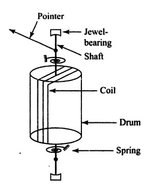
The permanent magnet moving coil (PMMC)-type instrument is the basic dc measuring instrument. In the instruments, a permanent magnet, generally of horseshoe type, creates a magnetic field in which a coil of fine wire of the number of turns is placed. The coil is wound on a very light aluminum drum and pivots on jewel bearings so that the coil is free to move when current flows through it. The current-carrying coil placed in the magnetic field experiences a torque and tries to turn. its free turning is restricted by spring tension attached to its shaft. The moving coil produces a defecting torque which is opposed to the control torque produced by the spring action. A simplified diagram of a PMMC type instrument is shown in the figure.
Its operating principle is the same as that of the D’Arsonval galvanometer. When a current flow through the coil, a magnetic field is produced which reacts with the magnetic field produced by the permanent magnet.
The current to be measured or a definite fraction of it proportional to the voltage to be measured is passed through the coil. A deflecting torque is produced on account of the reaction of the permanent magnetic field with the magnetic field produced by the coil. The direction of deflecting torque can be found by applying Flemming’s left-hand rule.
Advantages of PMMC Type instruments
Uniform scale
Since driving power is small, power consumption is low.
Due to aluminum or copper former, hysteresis loss is absent.
Very effective and reliable eddy current damping.
The torque-weight ratio is very high.
Due to the application of an intense polarized or unidirectional field, the stray magnetic field has no effect.
Using shunts or multipliers, ranges can be extended.
Disadvantages of PMMC Type Instrument
PMMC type of instrument can be operated in direct current only. In alternating current, the instrument does not operate because in the positive half the pointer experiences a force in one direction, and in the negative half, the pointer experiences the force in the opposite direction. Due to the inertia of the pointer, it remains in its zero position.
Compared to moving iron instruments, these instruments are costlier,
Friction error due to Jewel and pivot suspension, temperature, aging of control springs, and permanent magnets might introduce errors.
Ques.45. Which of the following can measure the resistance having the value below 1 Ohm most precisely?
Kelvin’s bridge is a modification of Wheatstone’s bridge and is used to measure values of resistance below 1Ω. In low resistance measurement, the resistance of the leads connecting the unknown resistance to the terminal of the bridge circuit may affect the measurement. In a typical Kelvin’s bridge, the range of resistance covered is 1Ω to 10 μΩ.
The Wheatstone’s bridge is not suitable for comparing two very low resistance such as metal rods because the junction resistances and resistances of connecting wires are larger compared to the low resistance to be measured.
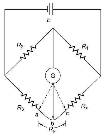
Consider the circuit in Fig., where Ry represents the resistance of the connecting leads from R3 to RX (unknown resistance). The galvanometer can b connected either to point c or to point a. When it is connected to point “a” the resistance Ry of the connecting lead is added to the unknown resistance Rx, resulting in too high indication for Rx
When the connection is made to point “c” Ry is added to the bridge arm R3 and the resulting measurement of RX is lower than the actual value because now the actual value of R3 is higher than its nominal value by the resistance Ry. If the galvanometer is connected to point “b” in-between points “c” and “a”, in such a way that the ratio of the resistance from “c” to “b” and the from “a” to “b” equals the ratio of resistances R1 and R2, then
Rcb/Rab = R1/R2
The actual equation of Kelvin’s bridge is
Rx = R1.R3 ⁄ R2
Ques.46. Which of the following quantities cannot be measured using a multimeter?
AC voltage
DC Current
Phase Angle✓
Resistance
A multimeter is a very useful electronic instrument that can be used for the measurement of three quantities, namely voltage, current, and resistance. This instrument can also be used for both dc and ac voltages and currents. Multimeters are available in both analog and digital forms. Although analog multimeters are being replaced by digital multimeters.
Ques.47. Which of the following materials when used as the viewing surface of a CRO gives a bluish glow?
Zinc Sulfide with copper as Impurity
Zinc sulfide with silver as an Impurity✓
Yttrium Oxide
Pure Zinc Sulfide
The actual conversion of light energy from the electricity occurs on the display screen when electrons strike the material called phosphor. A phosphor is a chemical that shines when exposed to electrical energy. A commonly used phosphor compound is zinc sulfide. When the pure zinc sulfide is struck by an electron beam, it gives a green glow. The exact color given by phosphor also depends on the presence of small amounts of impurities. For example, zinc sulfide with silver metal gives a blue glow in the form of an impurity, and copper metal gives a green glow in the form of impurity.
Ques.48. What is the percentage voltage error of a potential transformer with the system voltage of 11,000 V and having turns ratio of 100, if the measured secondary side voltage is 105 V?
2.75
3.55
4.76✓
9.09
System voltage i.e Nominal voltage = 11000 V
Voltage Transformation ratio of potential transformer is
V1/V2 = N1/N2
V1/105 = 100
Primary voltage = Turn ratio × Secondary voltage = 105 × 100 = 10500 V
Percentage of error is the Potential error
= (Nominal voltage − Primary voltage)/Primary voltage
(11000 − 10500)/10500
= 4.76%
Ques.49. Which of the following is the cause of the speed error in the induction type energy meter?
Incorrect Position of brake magnets✓
Incorrect adjustment of the position of shading bands
Slow but continuous rotation of an aluminum disc
Temperature variations
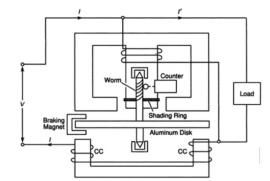
The energy meter is an integrating meter that measures the electrical energy consumed by a load. Induction-type energy meters are very commonly used to measure the electrical energy consumed in domestic, commercial, and industrial installations.
Principle
The basic principle of induction type energy meter is electromagnetic induction. When alternating current flows through two suitably located coils (current coil and voltage coil), it produces the rotating magnetic field which is cut by the metallic disc suspended near the coils. Thus, an emf is induced in the disc which circulates eddy currents in it.
Errors in induction type energy-meter
The following are the common errors that may creep into an energy meter:
Phase and speed errors
Frictional error
Creeping error
Temperature error
Frequency error
Speed error:- Due to the incorrect position of the brake magnet, the braking torque was not correctly developed. This can be tested when the meter runs at its full load current alternatively on loads of unity power factor and a low lagging power factor. The speed can be adjusted to the correct value by varying the position of the braking magnet towards the center of the disc or away from the center and the shielding loop. If the meter runs fast on inductive load and correctly on non-inductive load, the shielded loop must be moved towards the disc. On the other hand, if the meter runs slow on no inductive load, the brake magnet must be moved towards the center of the disc.
Phase Error:- The phase error is introduced because the shunt magnet flux does not lag behind the supply voltage by exactly 90° due to some resistance of the coil and iron losses. The angle of lag is slightly less than 90°. Because of this error, the torque is not zero at the zero power factor of the load therefore, the energy meter registers some energy even though the actual energy passing through the meter is zero at the zero power factor.
In order to remove this error, the flux produced by the shunt magnet should be made to lag behind the supply voltage exactly by 90°. This is accomplished by adjusting the position of the copper shading band provided on the central limb of the shunt magnet. An error on the fast side, under these conditions, can be eliminated by bringing the shading band nearer to the disc and vice versa.
Friction Error:- This error is introduced due to friction at the rotor bearing and in the register mechanism. Because of this error, an unwanted braking torque acts on the moving system and the meter registers less energy than the actual energy passing through it.
This error is compensated by placing two short-circuited bands on the outer limbs of the shunt magnet. These bands embrace the flux contained in the two outer limbs of the shunt magnet. An emf is induced and the current circulates through them. This causes phase displacement between the enclosed flux and the main gap flux. As a result of this, small driving torque is exerted on the disc solely by the pressure coil which compensates, for the frictional torque. The amount of this corrective torque is adjusted by the variation of the position of the two bands and it should be just sufficient to overcome the frictional torque without actually rotating the disc at on-load.
Creeping Error:- The slow but continuous rotation of the energy meter when only the pressure coil is excited and no current is flowing through the current coil is called creeping. This error may be due to excessive friction compensation, excessive voltage supply, stray magnetic field, etc.
In order to prevent creeping at no-load, two holes of the same radius are drilled in the disc on the opposite side of the spindle. This causes sufficient distortion of the field to prevent continuous rotation. The disc remains stationary when one of the holes comes under one of the poles of the shunt magnet.
Temperature Error:- By the change of temperature, the parameters of the coils change slightly which introduces a small error in the meter. However, this error is negligible and there is no need to provide any means to eliminate this error.
Frequency Error:- Since the energy meters are used normally at the fixed frequency, therefore they are designed and adjusted to have a minimum error at the declared supply frequency which is normally 50 Hz in India.
Ques.50. A circuit having a power factor of 0.8 consumes 20 W. What is the value of reactive power (in VAR) of the circuit?
10
15✓
20
25
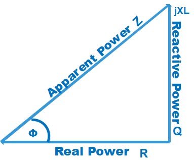
The power triangle or Impedance triangle of the AC circuit is shown Below
Cosφ = Base ⁄ Hypotenuse = Active Power ⁄ Apparent Power
Active Power = Apparent power × Cosφ
Sinφ = Perpendicular ⁄ Hypotenuse = Reactive Power ⁄ Apparent Power