Ques.81. The fuse is installed in which of the following wire?
- Neutral
- Phase✓
- Earth
- All of the above
A fuse is a protective device against an overcurrent fault. So we connect the fuse in series with phase as the load current flows through it and when an abnormal condition happens(overload)above the rated current of the fuse that melts down and breaks the circuit from electric potential. Now why do we connect it in phase only why not in Neutral? Suppose in the single-phase we did connect a fuse in neutral instead of phase when the fault is in the equipment then the fuse will blow in neutral also but the potential will be still present in the equipment as phase will be still present in the equipment. Also, a fuse should completely isolate the load or wiring from the supply by its burn-off or removed. Since, neutral is not a live conductor coming from the source, disconnecting a neutral line can only open the current path through neutral. But, the live phase still carries the charge. It always provides a live supply at the conductors or to the load.
Ques.82. The wave of the armature m.m.f in DC machine is_____
- Square
- Rectangular
- Triangular✓
- Sinusoidal
The armature MMF of a distributed armature winding of a dc machine is triangular in shape as shown in Fig. In a D.C. machine, the armature M.M.F. wave has its maximum value at fixed points between the main poles, and its chief effect is to increase the flux density on one side of the pole and reduce it on the other At GNA (Geometrical neutral axis) MMF Attends its maximum value MMF and at MNA ( Magnetic neutral axis) MMF Attends zero value, it is alternating in nature. At the MNA axis the armature conductors are situated in parallel with the field flux thus induced EMF is zero at that time and at GNA axis the armature conductors are situated at 90 ° with the field fluxes, between MNA and GNA the armature MMF slowly rises as the angle between an armature conductor and field flux increases the MMF induced on that conductor increases thus it creates a triangular form of armature MMF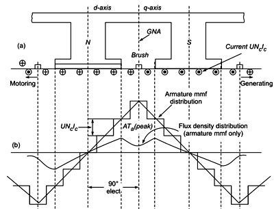
Ques.83. Lightwave travel with a velocity of___
- 3 × 1010cm/s
- 3 × 1012cm/s
- 3 × 1015cm/s
- 3 × 1018cm/s✓
Ques.84. Light is produced in electric discharge lamps by___
- Heating effect of current
- Magnetic effect of current
- Ionization in a gas or vapor✓
- Carbon electrodes
In electric discharge lamps, light is produced by the passage of an electric current through a vapor or gas rather than through a tungsten wire as in incandescent lamps. The light production by discharge sources is more efficient than the electric heating method used in filament lamps. Light is produced in electric discharge lamps by ionization in a gas or vapor.
Gas-discharge lamps are a family of artificial light sources that emit light by sending an electrical discharge through an ionized gas, i.e. plasma. Typically, such lamps are filled with a noble gas (argon, neon, krypton, and xenon) or a mixture of these gases. Most lamps are filled with additional materials, such as mercury, sodium, and metal halides.
Once ionization in the gas starts, the resistance to the flow of current reduces continuously, requiring lower voltage to maintain the flow of current. Thus, a gas discharge lamp possesses a negative resistance characteristic. To prevent the current from attaining an abnormally high value, a choke or a blast is used in the a.c. circuit. The choke provides the high ignition voltage initially as well as the current-limiting element in normal running. Because of the use of a choke in the circuit, the power factor of the gas discharge lamp is poor about 0.3 to 0.4.
There are two types of gas discharge lamps. In the first type, the color of the lamp depends on the gas or vapor used. The color of light from the sodium vapor lamp is yellowish, while the mercury vapor lamp radiates bluish-white colored light. The neon lamps give orange-pink light. In another type of gas discharge lamp, the inside of the tube of the gas discharge lamp is coated with a fluorescent material known as a phosphor. The color of the light depends on the phosphor used. This type of gas discharge lamp is known as the fluorescent lamp.
Ques.85. A DC generator can be termed as____
- Rotating amplifier✓
- Prime Mover
- Power Pump
- None of these
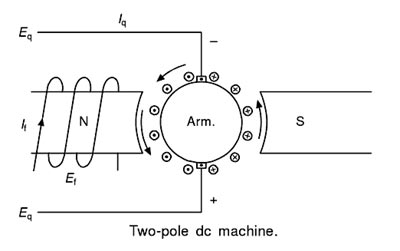
DC- generator or cross-field machines are also called rotating amplifiers which are DC machines with an additional brush set. The output power is controlled by varying the field current of the generator. If P2 is the output power and P1 is the input power to the field winding, the power amplification becomes P2/P1. The input power is usually 1 percent of output power and hence P2/P1= 100. There is a power amplification in the DC generator. Since it is rotating, the rotating amplifier is Derived. Depending on the degree of compensation, the cross-Geld generators can be classified as (i) metadyne and (ii) amplidyne. Metadyne Metadyne is a two-stage generator combined in a single machine T It saves the cost of the additional machine used in the earlier two cases and the overall size is also reduced. It is a two-stage rotating amplifier. For this purpose, the armature has to generate two types of currents. One is required to provide the excitation to develop the necessary magnetomotive force for the second stage and the second armature current to supply the power to the load or controlled machine. In cross-field machine two field fluxes are produced with an electrical or magnetic axis perpendicular to each other. To collect the electromotive forces generated by the two fluxes two sets of brushes are required. The other alternative is to use two opposite poles in the first stage and to use four poles for the second or the output stage. The word metadyne is used for cross-field machines. There are two versions of metadyne. In response to the constant input voltage, the metadyne convener can develop constant current output. Metadyne generator generally works with normal mechanical power. Amplidyne Amplidyne is somewhat similar to a metadyne generator. It is also a rotating amplifier. It amplified the input but it is not a stationary device like an electronic amplifier, magnetic amplifier or transformer. It has two stages of generation. But the two stages of generation are not provided by two different machines. Similar to the metadyne generator, the two stages are combined in a single machine. Amplidyne is considered a fully compensated two-stage dc generator. Due to part compensation, the compensating winding of amplidyne is not in the form of a single coil used by metadyne. 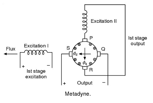
Ques.86. Arc blow is a welding defect that is encountered in
- Arc welding using DC current
- Arc welding using AC current✓
- Gas welding
- Thermit welding
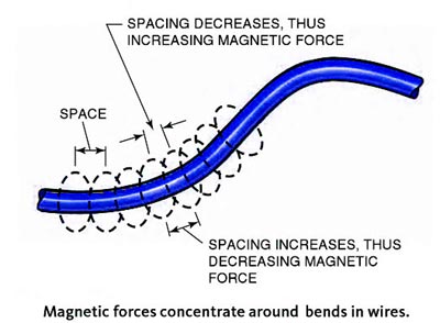
When electrons flow, they create lines of magnetic force that circle around the path of flow. These lines of magnetic force are referred to as magnetic lines of flux. They space themselves evenly along a current-carrying wire. If the wire is bent, the flux lines on one side are compressed together, and those on the other side are stretched out, as shown in Figure. The unevenly spaced flux lines try to straighten the wire so that the lines can be evenly spaced once again. The force that they place on the wire is usually small, so the wire does not move. However, when welding with very high amperages, 600 amperes or more, the force may actually cause the wire to move. The welding current flowing through a plate or any residual magnetic fields in the plate results in unevenly spaced flux lines. These uneven flux lines can, in turn, cause the arc between the electrode and the work to move during welding. The term arc blow refers to this movement of the arc. Arc blow makes the arc drift like a string would drift in the wind. Arc blow can be more of a problem when the magnetic fields are the most uneven such as when they are concentrated in corners, at the ends of plates, and where the work lead is connected to only one side of a plate. The more complex a weldment becomes, tt more likely arc blow will become a problem. Comply weldments can distort the magnetic lines of flux in unexpected ways. If you encounter severe arc blow during a weld, stop welding and take corrective measures to control or reduce the arc blow. Arc blow can be controlled or reduced by connecting the work lead to the end of the weld joint and then welding away from the work lead, Another way of controlling arc blow is to use to work leads, one on each side of the weld. The best we to eliminate arc blow is to use an alternating current. AC usually does not allow the flux lines to build long enough to bend the arc before the current changes direction. If it is impossible to move the work connection or to change to AC, a very short arc length can help control arc blow. A small tack weld or a change in the electrode angle can also help control arc blow.ARC BLOW
Ques.87. Which of the following has the highest value of thermal conductivity?
- Aluminum
- Brass
- Copper✓
- Iron
The physical parameter that characterizes and quantifies the material’s ability to conduct heat is called thermal conductivity. The SI unit of thermal conductivity is watts per meter-kelvin (W·m−1·K−1). Diamond has the highest value of thermal conductivity of 1000 W/m K at 20°C. The thermal conductivity of the copper is around 385.0 W/m K at 20°C. The thermal conductivity of aluminum is 205 W/m K at 20°C The thermal conductivity of Brass is 109 W/m K at 20°C The thermal conductivity of Iron is 79.5 W/m K at 20°C
Ques.88. During resistance welding heat produced at the joint is proportional to___
- Current
- Voltage
- I2R✓
- Volt-ampere
In the resistance welding (RW) process the weld is made by clamping the parts together between the welding machine’s electrodes. Then an electric current is passed through the parts to heat up the surfaces so they will fuse together. The welding current required to make a resistance weld must be at a very low voltage but high amperage. Pressure is always applied to ensure a continuous electrical circuit and to forge the heated parts together. Heat is developed in the assembly to be welded, and pressure is applied by the welding machine through the electrodes. During the welding cycle, the mating surfaces of the parts are heated to a plastic state just before melting and are forced together. The surfaces do not have to melt for a weld to occur. The parts are usually joined as a result of heat and pressure and not their being melted together. Fluxes or filler metals are not needed for this welding process. The heat produced in the weld may be expressed in the following formula: H = I2RT Where H = Heat I = Current T = Time for which current flows. Here, the total resistance offered to the flow of current is made up of: The current for resistance welding is usually supplied by either a transformer or a transformer/capacitor arrangement. The transformer, in both power supplies, is used to convert the high line voltage (low-amperage) power to the welding high-amperage current at a low voltage. A capacitor, when used, stores the welding current until it is used This storage capacity allows such machines to use a smaller size transformer. The required pressure or electrode force is applied to the workpiece by pneumatic, hydraulic, o mechanical means. The pressure applied may be as little as a few ounces (grams) for very small welders to tens o thousands of pounds (kilos) for large spot welders. Most resistance welding machines consist of the following three components: Depending upon the method of weld obtained and the type of electrodes used, the resistance welding is classified as:Resistance Welding

Ques.89. Which of the following is tetravalent?
- Quartz
- Diamond
- Germanium✓
- Antimony
Germanium is either divalent or tetravalent (i.e there are four electrons in the outer orbit of the atoms). in its compounds. The divalent compounds of germanium oxides, sulfides and all four halides are known and are either easily oxidized or reduced. Tetravalent germanium salts are more stable than the divalent ones. Antimony is H -a type of semiconductor and has the pentavalent bond (i.e there are five electrons in the outer orbit).
Ques.90. The pair of donor impurities for the semiconductor material is
- Arsenic and Antimony✓
- Arsenic and Argon
- Gallium and Helium
- Gallium and Indium
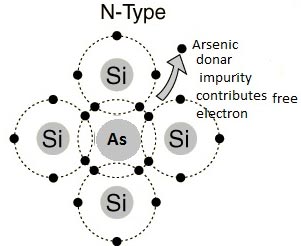
Extrinsic Semiconductor In order to change the properties of intrinsic semiconductors a small amount of some other material is added to it. The process of adding other material to the crystal of intrinsic semiconductors to improve its conductivity is called doping. The impurity added is called dopant. The doped semiconductor material is called an extrinsic semiconductor. The doping increases the conductivity of the basic intrinsic semiconductors hence the extrinsic semiconductors are used in practice for the manufacturing of various electronic devices such as diodes, transistors etc. Depending upon the type of impurities, the two types of extrinsic semiconductors are, N-TYPE Impurity The impurity material having five valence electrons is called the pentavalent atom. When this is added to an intrinsic semiconductor, it is called donor doping as each impurity atom donates one free electron to an intrinsic material. Such an impurity is called donor impurity. Examples of such impurities are arsenic, bismuth, phosphorous, Antimony, etc. This crests an extrinsic semiconductor with a large number of free electrons called an n-type semiconductor. Germanium and Silicon are tetravalent. The impurity atoms may be either pentavalent or trivalent, i.e., frog groups V and III of the periodic table. If a small quantity of a pentavalent impurity (having 5-electrons in tt outermost orbit) like Arsenic (As), Antimony (Sb) or Phosphorus (P) is introduced in Germanium, it replaces the equal number of Germanium atoms without changing the physical state of the crystal. Each of the four out of five valency electrons of impurity says Arsenic enters into covalent bonds with Germanium, while the fifth valence electron is set free to moo from one atom to the other as shown in Fig. The impurity is called donor impurity as it donates an electron and the crystal is called an N-type semiconductor. A small amount of Arsenic (impurity) injects billions of free electrons into Germanium thus it creasing its conductivity enormously. In an N-type semiconductor, the majority carriers of charge are the electrons and holes as minority carriers. This is because when donor atoms are added to a semiconductor, the extra free electrons give the semiconductor a greater number of free electrons than it would normally have.